ALLPCB


In the fast-paced world of digital circuit design, ensuring stable power delivery is a top priority. One of the biggest hurdles engineers face is managing noise and voltage fluctuations, which can disrupt the performance of sensitive components. This is where decoupling capacitors come into play. If you're struggling with decoupling capacitor selection, understanding capacitor ESR and ESL, or optimizing bypass capacitor PCB layout, you're in the right place. This blog post will guide you through the essentials of solving decoupling challenges, offering practical tips and detailed insights for better digital circuit design.
Whether you're a seasoned engineer or just starting out, we'll break down the complexities of decoupling capacitors and provide actionable advice to enhance your PCB designs. Let's dive into the details of how to tackle these capacitor quandaries head-on.
What Are Decoupling Capacitors and Why Do They Matter?
Decoupling capacitors, often called bypass capacitors, are essential components in digital circuit design. They act as a local energy reservoir, supplying quick bursts of current to integrated circuits (ICs) during sudden demand. This helps maintain a stable voltage supply and reduces noise that could interfere with signal integrity.
In digital circuits, ICs switch states rapidly, creating high-frequency noise and transient currents. Without proper decoupling, these fluctuations can cause voltage drops or spikes, leading to erratic behavior or even system failure. A well-placed decoupling capacitor smooths out these issues by filtering noise and stabilizing the power supply.
Key Challenges in Decoupling Capacitor Selection
Choosing the right decoupling capacitor for your digital circuit design isn't always straightforward. Several factors can impact performance if not considered carefully. Let's explore the main challenges and how to address them.
1. Capacitance Value: Finding the Right Size
The capacitance value determines how much charge a capacitor can store and release. For digital ICs, common values range from 0.01 μF to 1 μF, depending on the frequency of noise you're targeting. Low-frequency noise often requires larger capacitors (like 1 μF), while high-frequency noise is better handled by smaller values (like 0.1 μF or 0.01 μF).
A common approach is to use multiple capacitors of different values in parallel. For example, combining a 1 μF capacitor with a 0.1 μF capacitor can cover a wider range of frequencies. This ensures your circuit is protected from both low and high-frequency disturbances.
2. Understanding Capacitor ESR and ESL
Every capacitor has parasitic elements known as Equivalent Series Resistance (ESR) and Equivalent Series Inductance (ESL). These properties can limit the effectiveness of a decoupling capacitor, especially at high frequencies.
- Capacitor ESR: This is the internal resistance of the capacitor. High ESR can cause voltage drops during sudden current demands, reducing the capacitor's ability to stabilize the power supply. For digital circuits, aim for capacitors with low ESR, typically below 0.1 ohms for high-speed applications.
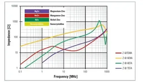
- Capacitor ESL: This represents the inductance within the capacitor and its leads. At high frequencies, ESL can dominate, making the capacitor behave more like an inductor and less like a noise filter. Low ESL capacitors, often in smaller packages like 0402 or 0201, are ideal for modern digital designs operating above 100 MHz.
Selecting capacitors with low ESR and ESL is critical for maintaining power integrity in high-speed digital circuits. Always check the manufacturer's datasheet for these specifications before making a choice.
3. Voltage Rating and Temperature Stability
Capacitors must be rated for a voltage higher than the maximum expected in your circuit to prevent breakdown. A general rule is to choose a capacitor with a voltage rating at least 50% higher than your supply voltage. For a 3.3V system, opt for a capacitor rated at 6.3V or higher.
Temperature stability is another factor. Ceramic capacitors, commonly used for decoupling, can lose capacitance at high temperatures or with DC bias. Look for capacitors with X7R or X5R dielectrics for better stability over a wide temperature range (-55°C to 125°C).
Optimizing Bypass Capacitor PCB Layout
Even the best decoupling capacitor won't perform well if its placement and layout aren't optimized. Poor PCB design can introduce parasitic inductance and resistance, negating the benefits of the capacitor. Here are key tips for effective bypass capacitor PCB layout.
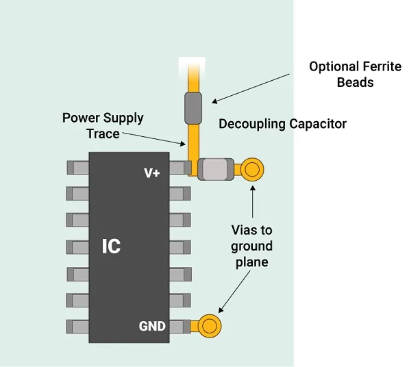
1. Place Capacitors Close to IC Power Pins
The closer a decoupling capacitor is to the IC's power pin, the better it can respond to transient current demands. Aim to place capacitors within 1-2 mm of the power pin to minimize loop inductance. The shorter the current path, the lower the inductance, which improves high-frequency performance.
2. Use Short, Wide Traces or Vias
Long, narrow traces between the capacitor and IC introduce unwanted inductance, reducing the capacitor's effectiveness. Use short, wide traces or multiple vias to connect the capacitor to the power and ground planes. This keeps the impedance low and ensures quick current delivery.
3. Connect to Ground and Power Planes Properly
In multi-layer PCBs, connect decoupling capacitors directly to the power and ground planes using vias. Avoid connecting multiple capacitors through a single via, as this can create a bottleneck and increase inductance. Each capacitor should have its own set of vias for optimal performance.
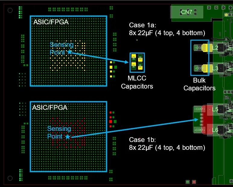
4. Distribute Capacitors for Multiple ICs
In designs with multiple ICs, distribute decoupling capacitors strategically across the board. Place bulk capacitors (10 μF to 100 μF) near the power entry point to handle low-frequency noise, and use smaller capacitors (0.1 μF to 1 μF) near each IC for high-frequency noise. This layered approach ensures comprehensive noise suppression.
Common Pitfalls in Digital Circuit Design with Decoupling Capacitors
Even with the best intentions, mistakes in decoupling capacitor implementation can lead to performance issues. Here are some common pitfalls to avoid in your digital circuit design.
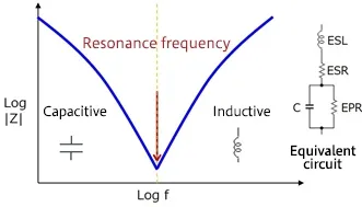
1. Overlooking Resonance Effects
Capacitors have a self-resonant frequency, beyond which they act more like inductors due to ESL. If multiple capacitors resonate at the same frequency, they can create impedance peaks, worsening noise issues. To avoid this, select capacitors with staggered resonant frequencies by using different capacitance values or package sizes.
2. Ignoring Power Delivery Network (PDN) Impedance
The overall impedance of your power delivery network plays a big role in decoupling effectiveness. A poorly designed PDN with high impedance can render even the best capacitors useless. Use simulation tools to analyze PDN impedance and ensure it remains below a target value, such as 0.1 ohms, across your operating frequency range (typically 1 kHz to 100 MHz for digital circuits).
3. Neglecting Component Aging and Derating
Over time, capacitors can degrade, losing capacitance or increasing ESR. This is especially true for electrolytic capacitors, though less common in ceramic types used for decoupling. Account for derating by choosing capacitors with higher initial capacitance or voltage ratings to ensure long-term reliability.
Practical Tips for Effective Decoupling in Digital Circuits
Now that we've covered the challenges and pitfalls, let's wrap up with some practical tips to improve your decoupling strategy in digital circuit design.
- Use a Combination of Capacitor Values: Pair larger capacitors (1 μF to 10 μF) with smaller ones (0.01 μF to 0.1 μF) to cover a broad frequency spectrum. This ensures both low and high-frequency noise are addressed.
- Prioritize Low ESR and ESL: For high-speed designs, choose ceramic capacitors with low parasitic values. Check datasheets for ESR below 0.1 ohms and minimize ESL by using smaller package sizes.
- Simulate Before Building: Use SPICE or PDN analysis tools to simulate your decoupling network. This helps identify potential issues like resonance or high impedance before you fabricate your PCB.
- Test Under Real Conditions: After assembling your board, measure voltage ripple and noise using an oscilloscope. Look for spikes exceeding 5-10% of your supply voltage (e.g., 0.165V for a 3.3V rail) and adjust capacitor placement or values as needed.
Conclusion: Mastering Decoupling for Robust Digital Designs
Decoupling capacitors are a cornerstone of reliable digital circuit design, but their effectiveness depends on careful selection and strategic PCB layout. By understanding key factors like capacitor ESR and ESL, choosing the right capacitance values, and optimizing bypass capacitor placement, you can significantly improve power integrity and reduce noise in your designs.
From tackling high-frequency noise with low-ESL capacitors to minimizing loop inductance through smart PCB layout, every detail counts. With the tips and insights shared in this blog, you're now equipped to handle decoupling challenges and build more robust digital circuits. Keep experimenting with different capacitor combinations and layouts to find what works best for your specific application.