 ALLPCB


Introduction
Modern vehicles integrate advanced electronics for features like advanced driver-assistance systems, electric powertrains, and connected infotainment. These systems require compact, lightweight components to optimize space and improve efficiency. Thin PCB automotive designs address these needs by providing reduced board thickness while maintaining functionality in harsh environments. Automotive PCB design must balance miniaturization with durability against heat, vibration, and electrical stress. Engineers face challenges in ensuring automotive PCB reliability when using thinner boards, as they can be more susceptible to warpage and mechanical failure. This article explores how thin PCBs meet automotive demands through targeted design and manufacturing strategies.
What Are Thin PCBs and Why They Matter in Automotive Electronics
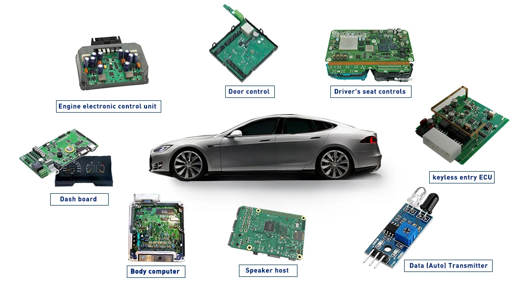
Thin PCBs refer to printed circuit boards with reduced overall thickness compared to standard profiles, enabling tighter integration in space-limited assemblies. In automotive applications, these boards support modules like engine control units, sensors, and battery management systems where bulkier designs would add unnecessary weight. The push for lighter vehicles enhances fuel economy in traditional cars and extends range in electric vehicles, making thin PCB automotive solutions essential. Beyond weight savings, thin boards facilitate better airflow for cooling in crowded enclosures. However, their slimmer construction demands careful material selection to uphold performance under operational stresses. Automotive engineers prioritize these boards to align with the industry's shift toward electrification and autonomy.
Key Design Principles for Thin PCBs in Automotive Environments
Automotive PCB design for thin boards starts with material choices that offer dimensional stability and thermal resilience. Laminates with higher glass transition temperatures suit high-temperature thin PCB applications near engines or exhaust systems. Low coefficient of thermal expansion materials minimize stress during temperature fluctuations, preserving trace integrity. For vibration resistance thin PCB performance, engineers match CTE between layers and substrates to prevent delamination. Stackup optimization reduces interlayer spacing while supporting high-density routing for complex signals. Adhering to IPC-6012DA guidelines ensures qualification for automotive-specific performance criteria.
Layer count influences thin PCB behavior; fewer layers simplify fabrication but limit routing density, while multilayers require precise prepreg control. Copper weight selection balances current handling with flexibility, avoiding excessive rigidity that could crack under flexure. Signal integrity demands controlled impedance, achieved through consistent dielectric thickness. Mechanical anchoring points, like edge supports, distribute loads evenly. Troubleshooting warpage involves symmetric stackups and controlled curing processes during lamination.

Addressing High-Temperature Challenges in Thin Automotive PCBs
Engine compartments expose electronics to prolonged elevated temperatures, testing high-temperature thin PCB capabilities. Thinner boards dissipate heat differently, relying on conduction through metals and convection via enclosures. Material degradation accelerates in slim profiles, so selecting resins with robust thermal stability proves critical. Design incorporates thermal vias and ground planes to spread heat from hotspots. Conformal coatings add a barrier against oxidation and moisture ingress at high temperatures. Reliability testing simulates these conditions to validate long-term operation.
Practical troubleshooting for thermal issues includes monitoring via temperature-rise simulations during design review. Oversized pads under power components improve heat spreading without thickening the board. Integration with heatsinks or thermal pads enhances dissipation in thin formats. Avoiding air voids in solder joints prevents hot spots that could fail prematurely. These strategies ensure thin PCBs endure automotive thermal cycles without compromising functionality.
Enhancing Vibration Resistance in Thin Automotive PCBs
Road and engine vibrations pose significant risks to thin PCB automotive assemblies, potentially causing fatigue in solder joints and traces. Vibration resistance thin PCB design emphasizes secure component mounting and board stiffening. Edge connectors and mounting holes positioned strategically absorb shocks. Flexible adhesives or potting compounds dampen resonances in vulnerable areas. IPC Class 3 criteria guide fabrication for high-reliability harsh environments, including mechanical endurance.
Testing per ISO 16750-3 verifies mechanical load tolerance, simulating real-world profiles. Troubleshooting reveals common failures like microcracks in copper; solutions involve wider traces and teardrop vias for stress relief. Multilayer boards with balanced copper distribution resist twisting better than singles. Conformal coatings reinforce surface protection against abrasion. Regular vibration profiling during prototyping identifies weak points early, allowing iterative improvements.
Best Practices for Automotive PCB Reliability with Thin Designs
Achieving automotive PCB reliability begins with holistic design review incorporating failure mode analysis. J-STD-001 requirements for soldered assemblies ensure joint strength in thin boards prone to flex. Component selection favors automotive-grade parts with robust leads for vibration tolerance. Routing avoids long unsupported spans, using ground pours for shielding and stability. Fabrication tolerances tighten for thin profiles to prevent bow and twist exceeding allowable limits.
Assembly best practices include low-stress soldering profiles to avoid board deformation. Post-assembly inspections check for voids or lifts under magnification. Environmental stress screening, like thermal shock, uncovers latent defects. Documentation of design rules facilitates repeatability across production runs. Engineers troubleshoot reliability dips by correlating field returns with accelerated life tests, refining stackups accordingly.
For high-density interconnects, microvias in thin multilayers demand laser drilling precision. Signal layers shield from EMI common in vehicles. Power distribution networks use thicker inner foils for efficiency. Firmware updates consider board flex impacts on connectors. These practices collectively elevate thin PCB automotive performance.
Conclusion
Thin PCBs play a pivotal role in advancing automotive electronics by enabling compact, lightweight designs without sacrificing essential performance. Automotive PCB design must integrate high-temperature tolerance, vibration resistance, and overall reliability through material savvy, precise stackups, and rigorous testing. Standards like IPC-6012DA, ISO 16750-3, and J-STD-001 provide the framework for success. Engineers benefit from practical troubleshooting to address warpage, joint fatigue, and thermal issues proactively. As vehicles evolve, thin PCB automotive solutions will continue driving innovation in safety and efficiency.
FAQs
Q1: What defines a thin PCB automotive design?
A1: Thin PCB automotive designs feature reduced board thickness to fit compact modules like sensors and controllers. Automotive PCB design emphasizes materials with low CTE for stability and high Tg for heat resistance. Vibration resistance thin PCB requires reinforced mounting and balanced stackups. Reliability hinges on testing per industry standards to ensure longevity in dynamic environments. These boards optimize weight and space critical for modern vehicles.
Q2: How do you improve vibration resistance thin PCB in automotive applications?
A2: Enhance vibration resistance thin PCB by using stiffeners, secure mounting holes, and conformal coatings. Automotive PCB reliability improves with CTE-matched layers to prevent delamination under shocks. Wider traces and teardrop transitions reduce fatigue points. Testing simulates road profiles to validate designs. Practical fixes include potting compounds for damping in high-stress areas.
Q3: What materials suit high-temperature thin PCB for vehicles?
A3: High-temperature thin PCB benefits from laminates with elevated glass transition points and low moisture absorption. Automotive PCB design selects these for engine bay proximity. They maintain integrity during thermal cycling. Pair with thermal vias for heat management. Troubleshooting involves verifying material datasheets against application profiles for optimal reliability.
Q4: Why is automotive PCB reliability crucial for thin boards?
A4: Automotive PCB reliability ensures thin boards withstand harsh conditions without failure, vital for safety systems. Thin profiles risk higher warpage, so standards guide qualification. Vibration and heat stress test limits. Best practices like symmetric stackups and robust soldering per J-STD-001 mitigate risks. Field-proven designs reduce warranty issues.
References
IPC-6012DA — Automotive Addendum to IPC-6012D Qualification and Performance Specification for Rigid Printed Boards. IPC.
J-STD-001 — Requirements for Soldered Electrical and Electronic Assemblies. IPC/JEDEC.
ISO 16750-3 — Road vehicles — Environmental conditions and testing for electrical and electronic equipment — Part 3: Mechanical loads. ISO.


