ALLPCB


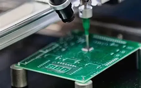
Why Drill Bit Selection Matters in PCB Manufacturing
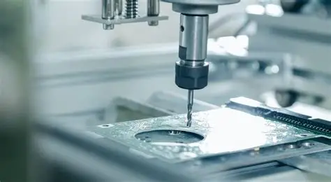
Mechanical drilling remains a foundational process in printed circuit board fabrication. Engineers rely on precise hole formation to create vias, mounting points, and component leads that support electrical connectivity and mechanical stability. Selecting the appropriate drill bits directly influences hole quality, production yield, and long-term board reliability. Poor bit choices can lead to excessive wear, inconsistent diameters, or surface defects that compromise downstream assembly steps. Factory teams therefore evaluate bit materials, geometries, and operating parameters against the specific laminate stack and production volume before committing to a drilling program.
Technical Principles of PCB Drill Bit Materials and Geometry
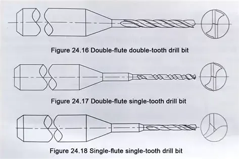
Carbide drill bits consist primarily of tungsten carbide particles sintered with a cobalt binder, providing the combination of hardness and toughness needed for repeated use in abrasive substrates. The material composition allows the cutting edges to maintain sharpness longer than high-speed steel alternatives when drilling through FR-4 or similar laminates. Bit geometry further refines performance: the point angle influences initial penetration and chip evacuation, while the helix angle controls how efficiently debris clears the hole. Flute design and web thickness also affect rigidity, which becomes critical when drilling small-diameter holes at high spindle speeds. These engineering parameters interact with the board material’s thermal and mechanical properties to determine the final hole wall condition.
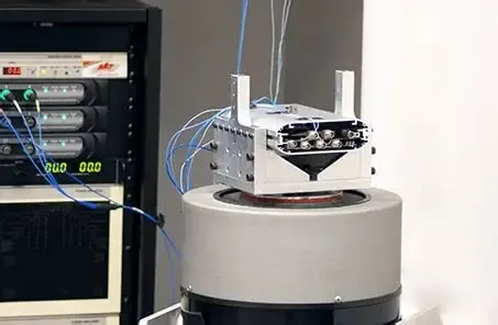
Drill Bit Speed, Feed, and PCB Drilling Techniques
Operating parameters must balance material removal rate against tool life and hole quality. Spindle speed, expressed in revolutions per minute, is selected according to the bit diameter and the surface speed tolerated by the carbide edge. Feed rate, typically measured in inches or millimeters per minute, controls how quickly the bit advances into the stack and influences chip formation. In practice, engineers adjust these values when moving between different laminate types or when stack thickness changes. Common techniques include peck drilling cycles that periodically retract the bit to clear chips and reduce heat buildup. Entry and exit foils or backup materials further stabilize the process and minimize burring on the outer layers.
Best Practices for Selecting and Maintaining PCB Drill Bits
Procurement and process teams begin by matching bit diameter to the finished hole size specified on the fabrication drawing, allowing for any plating buildup. They then verify that the chosen carbide grade and coating, if used, suit the expected number of hits per bit. Regular inspection of bit edges under magnification helps identify wear before it affects hole quality. When production volumes justify it, facilities implement tool-life tracking systems that record hits per bit and trigger replacement at predefined limits. Proper storage and handling prevent chipping or contamination that could introduce defects during drilling. These steps collectively reduce scrap and support consistent output aligned with factory quality systems.
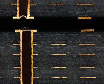
Quality Control and Process Monitoring in PCB Drilling
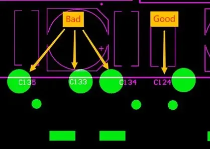
After drilling, panels undergo visual and automated optical inspection to detect issues such as rough hole walls, incomplete penetration, or positional drift. Cross-section analysis on sample boards confirms that hole wall roughness and smear levels remain within acceptable ranges for subsequent plating and assembly. Statistical process control charts track diameter variation and positional accuracy across lots, providing early warning when bit performance begins to degrade. When deviations appear, engineers review recent changes in bit supplier lots, spindle maintenance records, or laminate batches to isolate the root cause. This data-driven approach ensures that drilling remains a controlled and repeatable manufacturing step.
Conclusion
Effective drill bit selection for PCB mechanical drilling combines material science, geometric design, and disciplined process control. Carbide bits, properly matched to board construction and operated within validated speed and feed windows, deliver the hole quality required for reliable interconnects. Ongoing monitoring and adherence to established manufacturing discipline help sustain yield and support the performance expectations defined in relevant industry specifications. By treating bit selection as an integrated part of the overall fabrication workflow, engineering and production teams achieve consistent results across varying product mixes.
FAQs
Q1: What factors determine the choice of carbide drill bits for PCB drilling?
A1: Carbide drill bits are selected based on hole diameter, laminate type, stack height, and expected production volume. The material’s hardness provides wear resistance against glass reinforcement, while geometry parameters such as point angle and flute design influence chip evacuation and hole wall finish. Matching these characteristics to the specific drilling program helps maintain dimensional accuracy and surface quality throughout the run.
Q2: How does drill bit speed affect PCB drilling outcomes?
A2: Drill bit speed, in combination with feed rate, controls heat generation and chip formation during mechanical drilling. Appropriate speeds prevent excessive temperatures that could cause resin smear or delamination, while also extending bit life. Engineers adjust parameters when changing bit diameter or board material to keep the process within the stable operating window established during qualification.
Q3: What PCB drilling techniques improve hole quality in multilayer boards?
A3: Techniques such as peck drilling cycles and the use of entry and exit materials help maintain hole straightness and reduce burring. These methods manage chip removal and mechanical stress on the bit, which is especially important when drilling high-aspect-ratio holes. Consistent application of validated techniques supports the hole wall integrity needed for reliable plating adhesion.
Q4: Why is regular inspection of PCB drill bits important in manufacturing?
A4: Regular inspection detects edge wear or chipping before defects appear in production panels. Tracking hits per bit and reviewing hole quality metrics allows timely replacement, reducing the risk of out-of-specification holes. This practice supports overall process stability and helps meet the acceptance criteria for rigid printed boards.
References
IPC-6012E — Qualification and Performance Specification for Rigid Printed Boards. IPC, 2017
IPC-A-600K — Acceptability of Printed Boards. IPC, 2020
ISO 9001:2015 — Quality Management Systems. ISO, 2015