 ALLPCB


Wearable health devices continuously monitor parameters such as heart rate, blood oxygen levels, and activity metrics before transmitting the information to smartphones or cloud platforms. Bluetooth Low Energy serves as the primary wireless protocol in these applications because it delivers low power consumption while supporting the data rates required for real-time health tracking. PCB designers must integrate BLE modules with attention to radio frequency layout, power distribution, and mechanical constraints imposed by compact form factors. Proper implementation ensures reliable data transmission without excessive battery drain or signal degradation.
Why Bluetooth Connectivity Matters for Wearable Health PCBs
Wearable health products operate under strict size and weight limits that directly influence PCB stack-up and component placement. Bluetooth Low Energy wearable PCB designs prioritize energy efficiency to extend operational time between charges, often targeting multi-day use on a single battery. The protocol supports intermittent data bursts rather than continuous streaming, which aligns with the duty cycles typical of vital-sign monitoring. Engineers evaluate wireless protocol wearable options early in the design cycle because protocol choice affects antenna requirements, regulatory compliance, and overall system power budget. Reliable connectivity also supports secure transmission of sensitive physiological data, meeting expectations for privacy in medical applications.
Technical Principles of BLE Operation on Wearable PCBs
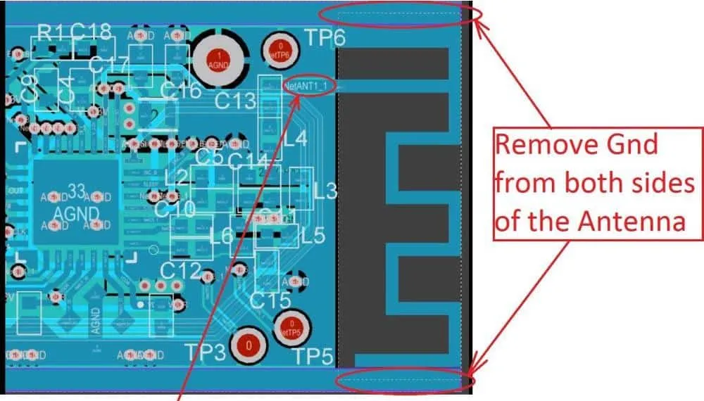
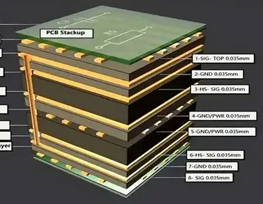
Bluetooth Low Energy operates in the 2.4 GHz ISM band using 40 channels with adaptive frequency hopping to mitigate interference. The protocol defines multiple physical layers and link-layer states that allow devices to remain in a low-power sleep mode until a connection event is scheduled. On the PCB, RF signal paths require controlled impedance traces, typically 50 ohms, to maintain signal integrity from the module output to the antenna. Ground planes beneath the RF section provide return paths and help contain electromagnetic fields. Component placement must minimize coupling between digital noise sources and sensitive receiver circuits. Power supply decoupling capacitors are positioned close to the module pins to suppress voltage droops during transmission peaks.
Security Mechanisms in Bluetooth Health Wearable Designs
Bluetooth security wearable health implementations rely on the protocol’s built-in encryption and authentication features. Pairing procedures establish shared keys using methods such as numeric comparison or out-of-band channels when available. Once paired, data packets are encrypted with AES-128 to protect confidentiality during transmission. Designers implement additional application-layer checks, including message authentication codes, to detect tampering or replay attacks. Secure boot and firmware update mechanisms further reduce the risk of unauthorized code execution on the wearable device. These layered protections address both over-the-air threats and physical access scenarios common in portable health products.
Factors Influencing Bluetooth Range in Wearable PCB Layouts
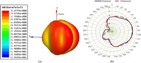
Bluetooth range wearable performance depends on transmitted power, receiver sensitivity, antenna efficiency, and the surrounding environment. PCB materials with higher dielectric constants can increase signal loss if the antenna is not properly matched. Ground plane size and shape affect radiation patterns, while nearby metal enclosures or battery packs can detune the antenna. Body tissue absorption further reduces effective range when the device is worn against the skin. Engineers simulate these effects using electromagnetic field solvers and validate performance through over-the-air testing in representative use conditions. Typical line-of-sight ranges for BLE in wearable applications fall between 10 and 50 meters depending on output power class and antenna design.
Best Practices for Integrating BLE Modules in Wearable PCBs
Module selection begins with evaluation of current consumption profiles across advertising, connection, and sleep states to match the target battery capacity. BLE module selection wearable decisions also consider available GPIO count, integrated flash memory size, and supported Bluetooth version features such as extended advertising. Layout guidelines recommend keeping the RF section isolated from high-speed digital traces and placing the antenna at the board edge when possible. Thermal reliefs and via stitching improve heat dissipation from the module during prolonged transmission periods. Compliance testing for emissions and susceptibility follows established procedures to confirm regulatory acceptance.
Design reviews incorporate signal integrity checks on all high-speed interfaces connected to the wireless subsystem. Firmware teams coordinate with hardware engineers to optimize connection parameters such as connection interval and slave latency for minimal power use. Environmental testing under temperature and humidity extremes verifies continued link stability, consistent with qualification approaches outlined in relevant industry standards.
Conclusion
Effective Bluetooth integration in wearable health PCBs combines protocol knowledge, careful RF layout, and robust security measures. Attention to power management, antenna design, and layout isolation directly influences both range and battery life. Following structured design practices helps engineers achieve reliable data transmission while satisfying the size and regulatory demands of medical wearable products.
FAQs
Q1: What considerations guide Bluetooth Low Energy wearable PCB layout for reliable performance?
A1: Layout prioritizes controlled impedance RF traces, adequate ground planes, and separation from digital noise sources. Engineers also evaluate antenna placement relative to the enclosure and human body to maintain acceptable link margins. These steps support consistent connectivity across varying usage conditions.
Q2: How does Bluetooth security wearable health design protect transmitted physiological data?
A2: Security features include AES-128 encryption of packet payloads and authenticated pairing procedures that establish trusted relationships between devices. Additional application-level checks further reduce risks of data interception or modification during transmission.
Q3: Which factors influence BLE module selection wearable applications?
A3: Selection criteria include average and peak current draw, supported Bluetooth features, available peripheral interfaces, and package size compatible with the target form factor. Thermal and regulatory compliance characteristics are also reviewed during the evaluation process.
Q4: What limits Bluetooth range wearable devices in real-world conditions?
A4: Range is constrained by transmit power class, antenna efficiency, PCB material losses, and absorption by nearby objects including the human body. Environmental interference and housing materials further affect the achievable distance between the wearable and the receiving device.
References
IPC-2221B — Generic Standard on Printed Board Design. IPC, 2012
JEDEC J-STD-020E — Moisture/Reflow Sensitivity Classification. JEDEC, 2014
IPC-6012E — Qualification and Performance Specification for Rigid Printed Boards. IPC, 2017





