 ALLPCB


Electric vehicles place printed circuit boards under demanding conditions that include wide temperature swings, continuous vibration, and exposure to moisture and chemicals. Manufacturers must verify that every PCB maintains electrical integrity and mechanical stability throughout the vehicle service life. Reliability testing forms a core part of factory quality systems, confirming that boards meet performance expectations before they reach assembly lines. These tests help prevent field failures that could affect vehicle safety or require costly recalls. By integrating structured testing protocols early in production, factories reduce defect rates and support consistent output quality.
Why PCB Reliability Testing Matters for Electric Vehicle Applications
Electric vehicle PCBs control critical functions such as battery management, power conversion, and motor drives. Any degradation in these boards can lead to reduced efficiency or sudden system shutdowns. Automotive environments accelerate aging mechanisms including solder joint fatigue, delamination, and conductor corrosion. Reliability testing identifies weak points before volume production begins, allowing process adjustments at the manufacturing stage. This proactive approach aligns with factory goals of delivering boards that perform reliably under real-world duty cycles. Without such verification, even well-designed boards may fail prematurely when subjected to combined stresses.
Core Automotive PCB Testing Methods
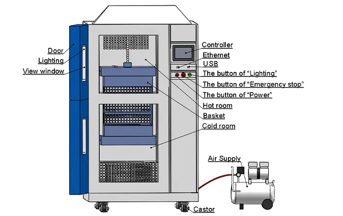
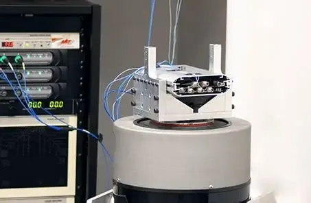
Accelerated life testing PCB protocols compress years of operation into weeks or months by applying elevated stresses. Engineers select temperature ranges, humidity levels, and voltage biases based on expected vehicle conditions. Data from these tests feed into statistical models that predict long-term behavior with reasonable confidence. Thermal shock testing PCB subjects boards to rapid temperature transitions between extreme hot and cold chambers. The goal is to reveal weaknesses in material interfaces and plated through-holes that might not appear under slower cycling. Vibration testing PCB evaluates mechanical robustness by mounting boards on shaker tables that simulate road-induced frequencies and amplitudes. Combined testing sequences often apply vibration while boards remain powered and thermally cycled to replicate actual operating profiles.
Standards That Guide PCB Reliability Testing
Factory teams reference established specifications to define test severity, sample sizes, and acceptance criteria. IPC-6012E outlines qualification requirements for rigid printed boards, including environmental stress tests that apply to automotive-grade products. JEDEC standards provide detailed procedures for temperature cycling and thermal shock that manufacturers adapt to electric vehicle board requirements. These documents ensure test methods remain consistent across suppliers and production lots. ISO 16750 complements the above by specifying environmental conditions and test procedures for electrical and electronic equipment in road vehicles. Adherence to these standards supports traceability and helps factories demonstrate compliance during customer audits.
Best Practices in Manufacturing Environments
Manufacturers integrate reliability testing into the production flow rather than treating it as a final gate. Early involvement of test engineers during design review allows selection of laminates and surface finishes that better withstand expected stresses. Process monitoring includes regular checks on plating thickness, via fill quality, and solder mask adhesion because these factors directly influence test outcomes. Sample boards pulled from each production batch undergo accelerated life testing PCB sequences to verify ongoing process stability. When failures occur, root-cause analysis focuses on material lots, equipment settings, or handling procedures. Corrective actions are documented and verified through repeat testing before resuming full output.
Practical Implementation of Combined Stress Testing
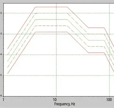
Many facilities employ sequential or simultaneous stress application to increase test realism. Boards first complete thermal shock testing PCB cycles, then move to vibration testing PCB while powered at nominal voltage. This sequence reveals interactions between thermal expansion mismatch and mechanical fatigue that single-stress tests might miss. Data logging captures resistance changes, insulation resistance, and functional performance throughout the test duration. Pass criteria typically require no opens, shorts, or parametric drift beyond defined limits. Factories maintain detailed records of test conditions, equipment calibration, and sample traceability to support continuous improvement initiatives.
Conclusion
Reliability testing remains essential for electric vehicle PCBs because it bridges the gap between laboratory design validation and real-world durability. By applying automotive PCB testing methods such as accelerated life testing PCB, thermal shock testing PCB, and vibration testing PCB under controlled conditions, manufacturers confirm that boards will maintain performance over extended service intervals. Reference to recognized standards ensures these activities are repeatable and auditable. The result is higher confidence in delivered products and fewer disruptions in vehicle assembly or field operation.
FAQs
Q1: What role do PCB reliability testing standards play in electric vehicle production?
A1: PCB reliability testing standards define the test methods, severity levels, and acceptance criteria that factories must follow to qualify boards for automotive use. They ensure consistent evaluation of thermal, mechanical, and electrical performance across different production sites and material suppliers.
Q2: How do automotive PCB testing methods differ from consumer electronics testing?
A2: Automotive PCB testing methods incorporate higher stress levels and combined environmental loads that reflect vehicle operating conditions such as wide temperature ranges and continuous vibration. Consumer electronics tests often use milder profiles because end-use environments are less severe.
Q3: Why is accelerated life testing PCB important for battery management systems?
A3: Accelerated life testing PCB accelerates aging mechanisms in battery management PCBs so manufacturers can predict long-term reliability within practical timeframes. The data supports design refinements and process controls before high-volume manufacturing begins.
Q4: What does thermal shock testing PCB reveal about board construction?
A4: Thermal shock testing PCB exposes weaknesses at material interfaces, plated through-holes, and solder joints caused by rapid temperature changes. Failures observed during this test often indicate issues with coefficient of thermal expansion mismatch or insufficient via robustness.
References
IPC-6012E — Qualification and Performance Specification for Rigid Printed Boards. IPC, 2017
JEDEC JESD22-A104 — Temperature Cycling. JEDEC
ISO 16750 — Road Vehicles — Environmental Conditions and Testing for Electrical and Electronic Equipment. ISO





