 ALLPCB


Introduction
Solder paste application remains one of the most critical steps in surface-mount technology assembly. Engineers often rely on step-up stencils to increase paste volume in specific areas, yet these tools introduce constraints in flexibility and process control. Alternative methods such as solder paste dispensing and jet printing address these limitations by enabling precise, localized deposition without requiring custom stencil modifications. For electric engineers working on mixed-technology boards or prototypes, understanding these options supports better decisions on throughput, yield, and rework capability. The following sections examine the technical mechanisms, practical trade-offs, and implementation considerations of these approaches.
Why Step-Up Stencil Alternatives Matter in Modern PCB Assembly
Step-up stencils provide additional paste height in selected apertures, but they can complicate design rules and increase the risk of bridging or insufficient volume elsewhere. Solder paste dispensing, jet printing, and stencil-less printing methods allow engineers to adjust deposit characteristics on a per-location basis without physical tooling changes. This flexibility proves especially valuable during design iterations or when assembling boards that combine fine-pitch components with larger thermal pads. Industry standards such as those from IPC emphasize consistent solder joint formation across varying component types. By exploring these alternatives, teams can maintain compliance while reducing dependency on multiple stencil revisions.
Related Reading: When and Why to Use a Step Up Stencil in Your PCB Project
Technical Principles of Solder Paste Dispensing and Jet Printing
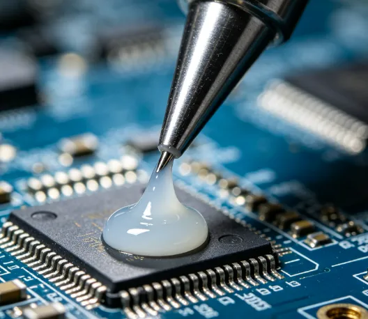
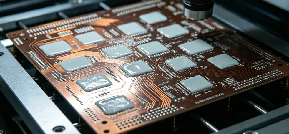
Solder paste dispensing operates through controlled extrusion of material from a syringe or cartridge under pneumatic or mechanical pressure. The process deposits a precise volume at each target pad, with parameters including needle diameter, pressure, and dwell time determining the final shape and height. Jet printing, by contrast, uses non-contact ejection of discrete droplets, allowing deposition on uneven surfaces or already-populated boards without risking stencil contact damage. Both techniques rely on the rheological properties of the paste, including viscosity and thixotropic index, to achieve repeatable results. Screen printing remains a baseline method for high-volume runs, yet it lacks the selective volume control offered by dispensing or jetting systems. Engineers evaluate these mechanisms against board warpage and component stand-off requirements to ensure adequate fillet formation.
Related Reading: Stencil Printing vs. Jet Printing: Which Method is Best for Your PCB Assembly Needs?

Practical Solutions and Best Practices for Implementation
Selecting the appropriate method begins with analyzing component mix and production volume. For low- to medium-volume builds or boards requiring frequent design changes, solder paste dispensing offers straightforward programming through coordinate data imported from the PCB layout. Jet printing excels in applications where stencil contact must be avoided, such as flexible circuits or assemblies with tall components already mounted. Engineers typically validate deposit volumes using automated optical inspection systems calibrated to IPC acceptance criteria. Process parameters should be documented and locked once optimized to maintain consistency across batches. When transitioning from step-up stencils, teams often conduct side-by-side trials to quantify differences in cycle time and defect rates.
Troubleshooting and Process Insights
Common issues with alternative methods include inconsistent deposit height caused by paste viscosity drift or needle clogging. Regular maintenance of dispensing equipment and controlled storage of solder paste mitigate these problems. Jet printing systems may require calibration of droplet velocity to compensate for variations in board surface energy. In mixed-technology boards, combining jet printing for fine-pitch areas with screen printing for larger regions can optimize overall process efficiency. Monitoring environmental factors such as temperature and humidity remains essential, as these influence paste behavior across all application techniques.
Conclusion
Alternative solder paste application methods expand the options available to electric engineers beyond conventional step-up stencils. Solder paste dispensing and jet printing deliver targeted volume control and adaptability that support evolving board designs and mixed-component assemblies. By aligning process selection with board complexity and production requirements, teams achieve reliable solder joints while adhering to established industry practices. Continued evaluation of these techniques helps maintain high assembly yields as technology requirements advance.
FAQs
Q1: What are the main step-up stencil alternatives for solder paste application?
A1: The primary alternatives include solder paste dispensing, jet printing, and stencil-less printing techniques. These methods enable selective volume adjustment without physical stencil modifications, offering greater flexibility for prototype and mixed-technology assemblies. Engineers evaluate them based on board layout complexity and required throughput.
Q2: How does jet printing differ from traditional screen printing in solder paste application?
A2: Jet printing deposits discrete droplets through non-contact ejection, allowing application on populated or uneven surfaces. Screen printing uses a mesh and squeegee to force paste through apertures in a single pass. The choice depends on production volume and the need for localized volume control.
Q3: When should engineers consider solder paste dispensing over stencil-based methods?
A3: Solder paste dispensing becomes advantageous for low-volume runs, frequent design changes, or boards with varying pad sizes that would otherwise require multiple stencil steps. It supports precise per-pad adjustments and reduces tooling costs associated with stencil fabrication.
Q4: What industry standards guide the evaluation of alternative solder paste application methods?
A4: Standards from IPC and JEDEC provide acceptance criteria for solder paste volume, shape, and resulting joint quality. These guidelines help ensure that dispensing or jet printing processes meet the same reliability expectations as conventional stencil printing.
References
IPC J-STD-005A — Requirements for Soldering Pastes. IPC, 2012
IPC-A-610G — Acceptability of Electronic Assemblies. IPC, 2017
J-STD-001G — Requirements for Soldered Electrical and Electronic Assemblies. IPC, 2017


