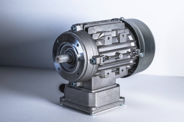
A shaft is a cylindrical component, typically metallic, that supports rotating parts and transmits motion, torque, or bending moments. It is commonly used in machinery to mount parts that perform rotary motion. Shafts are generally round but can occasionally be square.
Shaft Classification
Shafts are categorized based on their axis shape into straight shafts, crankshafts, and flexible shafts. This article focuses on straight shafts, which are further divided into three types based on load conditions:
- Rotating shafts: These bear both bending moments and torque, common in devices like speed reducers.
- Mandrels: These support rotating parts and bear only bending moments without transmitting torque. Some mandrels rotate (e.g., railway vehicle axles), while others are stationary (e.g., pulley supports).
- Transmission shafts: These primarily transmit torque without bearing bending moments, such as long optical shafts in crane mechanisms or automotive drive shafts.
Shaft materials are typically carbon steel or alloy steel, though ductile iron or alloy cast iron may also be used. A shaft¡¯s performance depends on its strength, stiffness, and, at high speeds, vibrational stability.
Shaft Materials
Carbon steel and alloy steel are the most common shaft materials. Carbon steel is cost-effective, less sensitive to stress concentrations, and offers good mechanical properties, making it widely used. Shaft blanks are typically made from rolled round steel or forgings. Forged blanks provide uniform internal structure and higher strength, making them suitable for critical applications.
Shaft Structural Design
Structural design determines a shaft¡¯s shape and dimensions, a critical step in shaft engineering. It involves considerations like the type, size, and position of mounted parts, fixing methods, load characteristics (nature, direction, magnitude, and distribution), bearing types and sizes, blank material, manufacturing and assembly processes, installation, transportation, and deformation. Designers may develop multiple schemes for comparison to select the optimal design. General design principles include:
- Minimize material use and weight by adopting equal-strength shapes or cross-sections with high section moduli.
- Ensure precise positioning, stability, assembly, disassembly, and adjustment of parts on the shaft.
- Implement measures to reduce stress concentrations and enhance strength.
- Facilitate manufacturing and ensure precision.
Axial Positioning and Fixing of Shaft Components
Common methods for axially positioning and securing components on a shaft include shaft shoulders, shaft rings, locking circlips, sleeves, round nuts with stop washers, elastic circlips, shaft-end retainers, and conical surfaces.
Shaft Maintenance
Correcting Shaft Bending Deformation
Excessive shaft deformation can be corrected using cold pressing or localized flame heating. Proper support during correction is critical to avoid stress concentrations, particularly at stepped shaft corners.
Repairing Journal Wear
Journal wear is typically addressed by grinding to correct geometric errors, followed by metal spraying or brush plating. In severe cases, welding or sleeving may be used, with sleeves fitted using interference fits.
Repairing Splines, Keyways, and Threads
Worn spline teeth can be repaired using gas welding or surfacing, followed by milling new splines based on the worn profile. Damaged keyways can be enlarged or filled by welding, then fitted with a new key. Thread damage requires welding and re-threading.
 ALLPCB


