ALLPCB


Components
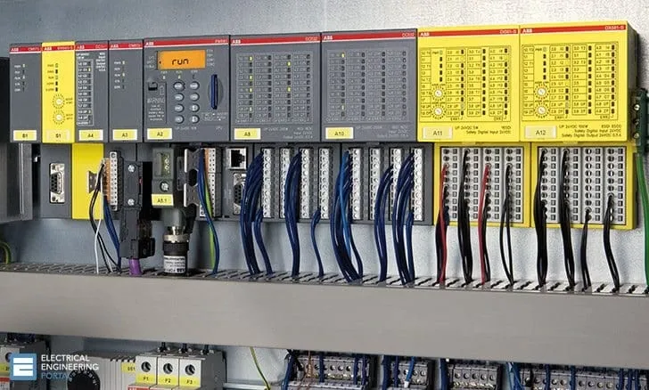
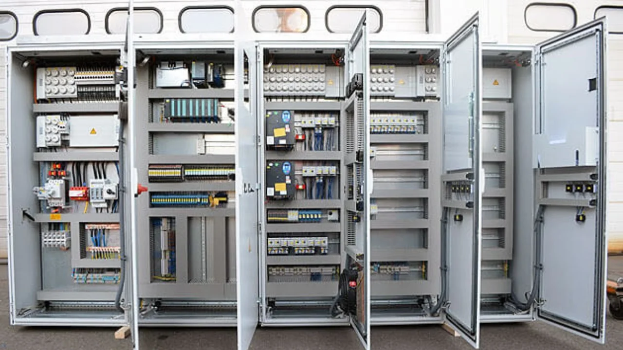
A PLC control cabinet typically includes:
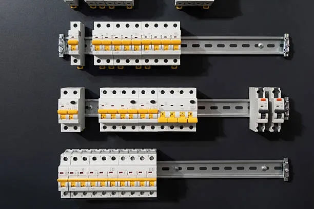
- Air circuit breaker: a main circuit breaker that controls the cabinet power.
- PLC: selection depends on the project. For small projects an integrated PLC may be sufficient; for larger projects a modular PLC with expansion modules or redundancy may be required.
- 24 V DC power supply: a 24 V DC switching power supply. Many PLCs have an internal 24 V DC supply; use an external supply only if required.
- Relays: PLC outputs can often drive control circuits directly, but relays may be needed when voltage levels differ. For example, if the PLC output is 24 V DC but the controlled circuit requires a 220 V AC signal, use a relay driven by the PLC to switch the 220 V AC line.
- Terminal blocks: necessary for wiring and signal distribution; quantity depends on the number of signals.
- Additional components as required: e.g., extra breakers for powering field instruments or small junction boxes, network switches for connecting PLCs to a host, etc.
Applications
Typical applications include water treatment, constant-pressure water supply, air compressors, fans and pumps, central air conditioning, port machinery, machine tools, boilers, paper machines, and food processing equipment.
Overview
PLC control cabinets are used for equipment and process automation and support networked communications. They can interface with DCS via Modbus, Profibus and other protocols, and with industrial PCs and Ethernet for control and monitoring. Cabinets can be configured for single-cabinet control or multiple cabinets connected via industrial Ethernet or fieldbus to form distributed control systems.
Operating Conditions
- Supply voltage: 24 V DC; single-phase AC 220 V (-10%, +15%), 50 Hz.
- Protection rating: IP41 or IP20.
- Ambient temperature: 0°C to 55°C, avoid direct sunlight.
- Relative humidity: less than 85% (no condensation).
- Avoid strong vibration sources; prevent frequent or continuous vibrations in the 10–55 Hz range.
- Avoid corrosive or flammable gases.
Basic Structure
A programmable logic controller is essentially a computer dedicated to industrial control. Its hardware architecture is similar to a microcomputer and typically consists of:
- Power supply
- Central processing unit (CPU)
- Memory
- Input/output interface circuits
- Function modules
- Communication modules
Working Principle
When a PLC is running, its operation is generally divided into three phases: input sampling, user program execution, and output refresh. Completing these three phases constitutes one scan cycle. During operation, the CPU repeatedly executes these phases at a fixed scan rate.
1. Input sampling
During input sampling the PLC sequentially reads all input states and data and stores them in the corresponding locations in the I/O image table. After input sampling, the PLC proceeds to program execution and output refresh. Changes to physical inputs during these two phases do not alter the values stored in the I/O image table. Therefore, if an input is a pulse, its pulse width must be longer than one scan cycle to ensure it is reliably sampled.
2. User program execution
During program execution the PLC scans the user program (ladder logic) from top to bottom. For each rung it evaluates the contact network (left side) first, performing logical operations in a left-to-right, top-to-bottom order. Based on the result, it updates the corresponding coil status in system RAM, or updates the corresponding bit in the I/O image table for outputs, or determines whether to execute special function instructions.
Only input points in the I/O image table remain unchanged during execution; output points and internal devices in the I/O image table or system RAM may change. Results from rungs above can affect rungs below that reference the same coils or data. Conversely, changes made by lower rungs do not influence higher rungs until the next scan cycle.
Using immediate I/O instructions allows direct access to I/O points. When immediate I/O is used, the input image register is not updated; the program reads values directly from the I/O module and the output image register is updated immediately, which differs from the normal scan behavior.
3. Output refresh
After program scanning, the PLC enters the output refresh phase. During this phase the CPU updates all output latches according to the I/O image table and drives the external devices through the output circuits. This is when physical outputs are actually asserted.
Functional Characteristics
Key characteristics of PLCs include:
- Flexible system architecture and easy expansion. Well suited for discrete (switching) control and capable of closed-loop control such as PID for continuous processes. PLCs can be integrated with higher-level systems (e.g., DDC, DCS) for comprehensive process automation.
- Ease of use and simple programming. Programming is typically done with ladder diagrams, function block diagrams, or instruction lists, allowing short development cycles and straightforward on-site commissioning. Programs can be modified online without changing hardware.
- Robust operation with strong anti-interference capabilities and high reliability suitable for harsh industrial environments.