ALLPCB


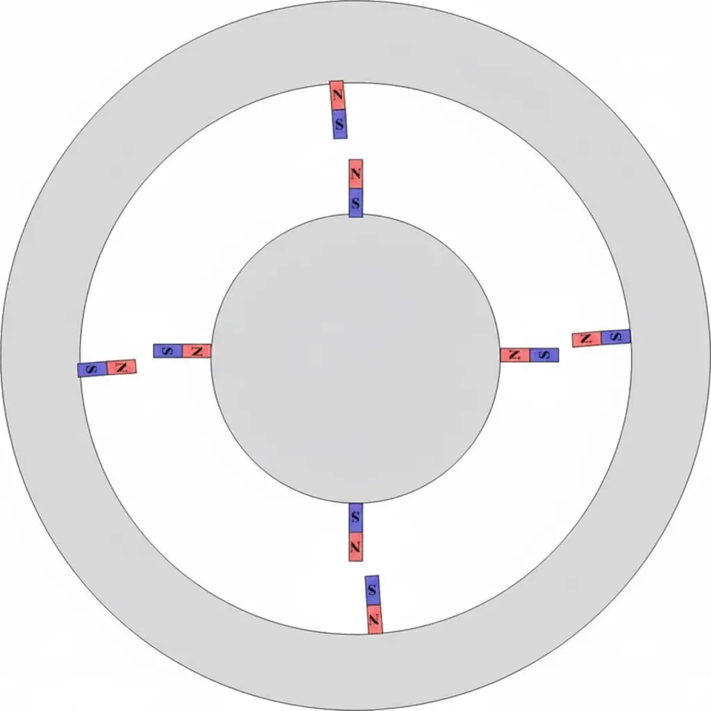
Basic motor model
The basic principle of all motors is shown below:
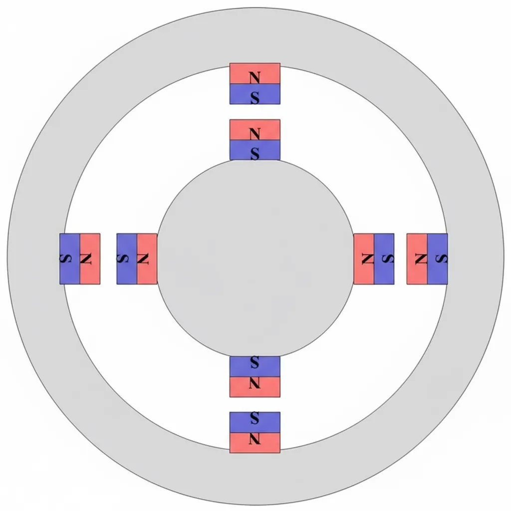
Two gray wheels represent the stator and the rotor. Which one is the stator and which one is the rotor can be chosen arbitrarily. Fundamentally, if one wheel is turned, the other tends to follow, like opposite poles of magnets attracting in basic physics.
Misalignment creates torque
In the figure the magnets are aligned and tightly attracted. If their relative angle is shifted, for example:
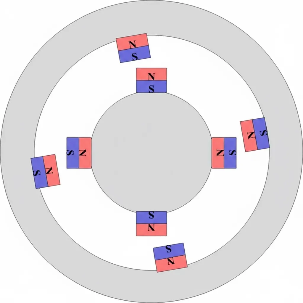
The configuration looks unstable, as if something will happen when released. That is force. Force times distance is torque. If you rotate the outer shell by hand, the inner wheel will follow and the motor turns. All AC motors are driven by a rotating magnetic field produced by balanced three-phase currents. In the following examples the outer magnetic field rotates and drives the inner rotor.
From the two figures we can draw some conclusions:
- When the magnets are exactly aligned, the motor will not turn; the system feels stable.
- When the magnets are slightly offset, the motor can rotate.
- When the magnets are offset too much, the available force may be insufficient to drive rotation.
- If the external field rotates much faster than the rotor starts from zero, the rotor may only oscillate and fail to synchronize.
Control objectives: position and field strength
To make the rotor rotate smoothly, the rotating external magnetic field must be controlled properly. It cannot be too fast or too slow; it must be advanced step by step according to the rotor state. That is the essence of motor control.
Consider the issue of alignment: if the magnets are too close or too far in angle, torque is low. What relative position yields the maximum torque? That question motivates the Park transform and the DQ axes, which let us analyze how spatial position affects torque.
The size of the magnetic field also matters. In reality the strength of the rotating magnetic field is produced by three-phase currents, so changing the amplitude of the sinusoidal currents will change the field strength. For permanent-magnet motors the rotor magnets are fixed, but the stator field strength is still adjustable via current. This will be discussed later.
In summary, two key factors determine motor behavior:
- Magnetic field strength
- Relative spatial position of rotor and stator fields
These two factors are coupled, which makes analysis difficult. If the field strength increases while the relative position also changes, it is hard to tell which effect dominates. Park transform and the DQ axis framework provide a convenient way to decouple these effects.
Park transform and DQ axes
The rotor has a magnetic field and the stator produces a magnetic field. Torque ultimately depends on the magnitudes and directions of these two field vectors.
All motors, including DC and various AC types, produce torque proportional to the cross product of rotor and stator magnetic field vectors. Geometrically, the torque is proportional to the area of the parallelogram formed by the two field vectors. If the fields are aligned, the parallelogram area is zero and there is no torque. If they are misaligned, a nonzero area generates torque.
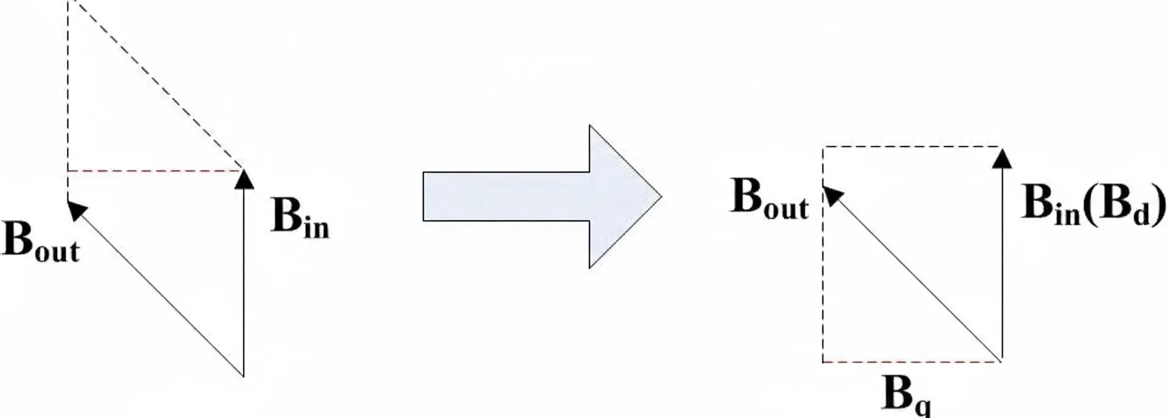
A parallelogram can be decomposed into a rectangle. We define the component of the stator field that is aligned with the rotor field as the d-axis field (d for direct), and the component orthogonal to it as the q-axis field (q for quadrature, i.e. 90 degrees). The two components Bd and Bq determine the rectangle sides, and their product determines the torque.
From current to torque
Magnetic field is produced by current, and inductance relates current to magnetic flux. The Park transform converts the three-phase quantities of the real motor into two orthogonal DQ components. If the DQ-axis inductances are known and the currents are measured, the DQ magnetic field components can be inferred. From those you obtain force and torque, and by controlling current you control torque and therefore speed.
The conceptual chain is:
current -> magnetic field -> force -> torque -> speed
By controlling the D-axis current Id and the Q-axis current Iq, you independently control Bd and Bq, which correspond to the two sides of the rectangle whose area is torque. The DQ pair forms a vector, so this approach is called vector control, or field-oriented control (FOC).