 ALLPCB


Reflow soldering is a critical process in PCB assembly, but the choice of PCB material can significantly influence its success. Materials like FR-4, high Tg laminates, and others with varying thermal conductivity and coefficient of thermal expansion (CTE) can impact outcomes, leading to challenges such as PCB warpage or poor solder joint reliability. In this blog, we’ll explore how PCB material properties affect reflow soldering and provide practical insights to overcome common issues.
At ALLPCB, we understand the importance of selecting the right materials for your project to ensure high-quality results. Let’s take a detailed look into how PCB materials interact with the reflow soldering process, focusing on key factors like thermal conductivity, CTE, and more.
Understanding Reflow Soldering and Its Challenges
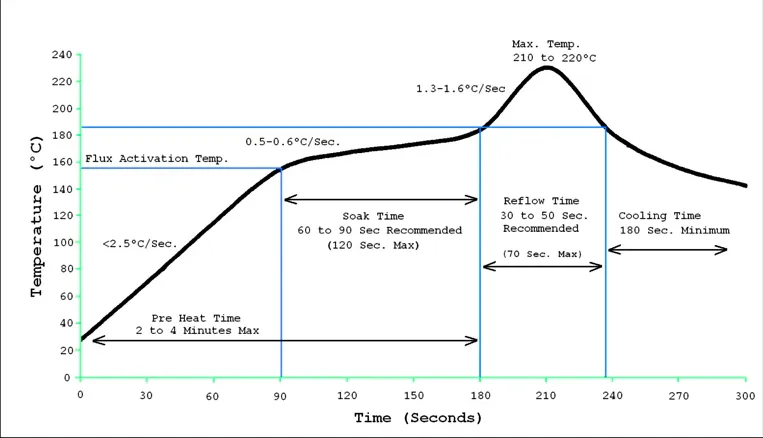
Reflow soldering is a widely used technique in electronics manufacturing to attach surface-mount components to a printed circuit board (PCB). It involves applying solder paste to the PCB, placing components, and then heating the assembly in a reflow oven. The heat melts the solder, creating strong electrical and mechanical connections as it cools.
However, this process isn’t without its hurdles. Common reflow soldering challenges include uneven heating, solder joint defects like voids or cracks, and PCB warpage. These issues often stem from the material properties of the PCB itself. For instance, a material with poor thermal conductivity might cause uneven temperature distribution, while a high CTE mismatch between the PCB and components can lead to stress and deformation during heating and cooling cycles.
Understanding how PCB material impacts these challenges is the first step toward optimizing your design and manufacturing process. Let’s break down the key material properties that play a role in reflow soldering performance.
Key PCB Material Properties Affecting Reflow Soldering
The choice of PCB material directly influences how the board behaves under the high temperatures of reflow soldering. Below, we’ll discuss the most critical properties and their effects.
1. Thermal Conductivity of PCB Materials
Thermal conductivity measures how well a material transfers heat. In reflow soldering, a PCB material with high thermal conductivity ensures even heat distribution across the board, reducing the risk of hot spots or cold areas that can lead to defective solder joints.
For example, standard FR-4, a common PCB material made of woven fiberglass and epoxy resin, has a thermal conductivity of about 0.25 to 0.3 W/m·K. This is relatively low compared to alternatives like metal-core PCBs, which can reach 1 to 4 W/m·K or higher. During reflow soldering, FR-4 might struggle to distribute heat evenly, especially in densely populated boards, potentially causing components to experience different temperatures and leading to inconsistent soldering results.
2. Coefficient of Thermal Expansion (CTE)
The coefficient of thermal expansion (CTE) indicates how much a material expands or contracts with temperature changes. During reflow soldering, the PCB and its components heat up to temperatures often exceeding 200°C (392°F) and then cool down. If the CTE of the PCB material differs significantly from that of the components or solder, it creates mechanical stress, which can result in cracked joints or PCB warpage.
For instance, FR-4 has a CTE of about 14-17 ppm/°C in the X-Y direction and 70-85 ppm/°C in the Z-direction. Many components, like ceramic capacitors, have a much lower CTE (around 6-10 ppm/°C). This mismatch can cause stress at the solder joints during thermal cycling, potentially leading to failures over time. Materials with a CTE closer to that of the components can minimize these risks.
3. Glass Transition Temperature (Tg) and High Tg Materials
The glass transition temperature (Tg) is the point at which a PCB material transitions from a rigid to a more flexible state. Standard FR-4 has a Tg of around 130-140°C, which is below typical reflow soldering temperatures for lead-free solder (around 217-260°C). At these temperatures, standard FR-4 can soften, increasing the risk of deformation or warpage.
High Tg materials, with Tg values of 170°C or higher, are designed to withstand these elevated temperatures better. They remain more stable during reflow soldering, reducing the likelihood of structural issues. For lead-free soldering processes, which require higher temperatures than traditional lead-based soldering, high Tg materials are often a preferred choice to maintain board integrity.
4. Moisture Absorption and Its Role in Warpage
PCB materials can absorb moisture from the environment, especially if not stored properly. During reflow soldering, this moisture turns into vapor, creating internal pressure that can cause delamination or warpage. FR-4, for example, has a moisture absorption rate of about 0.1-0.2%, which might seem small but can still lead to problems under high heat.
Materials with lower moisture absorption rates or proper pre-baking before soldering can mitigate these risks. Pre-baking the PCB at 120-150°C for a few hours can drive out absorbed moisture, ensuring a more stable reflow process.
Common PCB Materials and Their Performance in Reflow Soldering
Now that we’ve covered the key properties, let’s look at how specific PCB materials perform during reflow soldering and the challenges they present.
FR-4: The Industry Standard
FR-4 is the most widely used PCB material due to its balance of cost, electrical insulation, and mechanical strength. However, as discussed earlier, its low thermal conductivity and moderate Tg can pose challenges during reflow soldering. Uneven heat distribution and potential softening at high temperatures can lead to warpage, especially in larger or thicker boards.
For many standard applications, FR-4 works well, but for high-density or lead-free soldering projects, additional precautions like optimizing the reflow profile or using high Tg variants are necessary.
High Tg FR-4: Enhanced Stability
High Tg FR-4 materials are an upgrade over standard FR-4, offering better thermal stability for lead-free soldering. With a Tg of 170-180°C or higher, these materials resist deformation better at reflow temperatures. They are particularly useful for applications requiring multiple reflow cycles, as they maintain structural integrity under repeated thermal stress.
While high Tg materials are more expensive than standard FR-4, the investment can save costs by reducing defects and improving reliability in demanding projects.
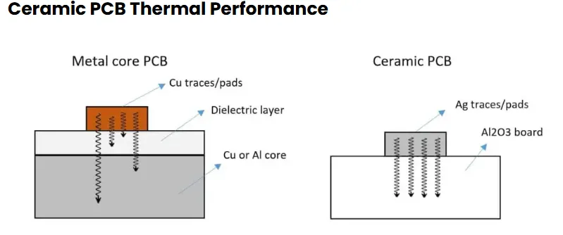
Metal-Core and Ceramic-Based Materials
For applications requiring superior heat dissipation, metal-core PCBs (MCPCBs) or ceramic-based materials are often used. MCPCBs, with a metal base layer like aluminum, have thermal conductivity values up to 10 times higher than FR-4, ensuring excellent heat distribution during reflow soldering. This minimizes thermal gradients and reduces the risk of warpage.
Ceramic materials, though less common due to cost, offer even better thermal and CTE properties, closely matching those of many components. However, their brittleness and high cost limit their use to specialized high-performance applications.
Reflow Soldering Challenges Linked to PCB Material
Let’s dive deeper into specific reflow soldering challenges caused by PCB material properties and how they manifest in the manufacturing process.
PCB Warpage: A Major Concern
PCB warpage occurs when a board deforms under thermal stress, often due to uneven expansion or contraction. This is closely tied to CTE mismatch and low Tg values. Warpage can misalign components, create poor solder joints, or even cause mechanical failure in extreme cases.
For example, a study on PCB assembly reliability found that warpage can increase by up to 50% when using standard FR-4 in lead-free reflow processes compared to high Tg materials. To combat this, designers can choose materials with better thermal stability or adjust the reflow profile to minimize rapid temperature changes.
Solder Joint Defects Due to Thermal Stress
Thermal stress from CTE mismatch can lead to solder joint defects like cracks or voids. During cooling after reflow, if the PCB contracts more than the components, it pulls on the solder joints, weakening them. Over time, this stress can cause failures, especially in applications with frequent thermal cycling.
Using materials with a CTE closer to that of the components or incorporating stress-relief features in the design can help reduce these defects.
Uneven Heating and Solderability Issues
Materials with low thermal conductivity, like standard FR-4, can cause uneven heating across the board. Some areas might reach peak reflow temperatures while others lag, leading to incomplete solder melting or cold joints. Adjusting the reflow oven settings to include a longer preheat phase can help, but choosing a material with better heat transfer properties is often a more effective solution for complex designs.
Practical Tips for Optimizing PCB Material Selection for Reflow Soldering
Selecting the right PCB material can make a significant difference in overcoming reflow soldering challenges. Here are some actionable tips to guide your decision:
- Match CTE Values: Choose a PCB material with a CTE similar to your components to minimize thermal stress. For high-reliability applications, consider materials like polyimide or high Tg laminates.
- Prioritize High Tg for Lead-Free Soldering: Lead-free soldering requires higher temperatures, so opt for high Tg materials to prevent softening or warpage during the process.
- Consider Thermal Conductivity: For heat-intensive designs, explore metal-core or other high-conductivity materials to ensure even heat distribution.
- Control Moisture: Store PCBs in a dry environment and pre-bake them before reflow soldering to remove absorbed moisture and prevent delamination.
- Optimize Reflow Profiles: Work with your manufacturing team to adjust the reflow oven settings, such as extending the preheat phase, to accommodate the thermal properties of your chosen material.
Conclusion: Making Informed Material Choices for Reflow Soldering Success
The impact of PCB material on reflow soldering cannot be overstated. Properties like thermal conductivity, CTE, and Tg directly influence the quality of solder joints, the risk of PCB warpage, and the overall reliability of the assembly. By understanding these factors and selecting the right material—whether it’s standard FR-4, high Tg laminates, or advanced metal-core options—you can significantly reduce reflow soldering challenges.
At ALLPCB, we’re committed to helping you navigate these choices with expert guidance and high-quality materials tailored to your needs. Whether you’re working on a simple prototype or a complex high-performance design, the right PCB material is the foundation of a successful reflow soldering process. Make informed decisions, and you’ll see the difference in your final product’s performance and durability.


