 ALLPCB


In the fast-evolving world of electronics, rigid-flex PCBs are a game-changer, combining the stability of rigid boards with the adaptability of flexible circuits. One of the most critical aspects of designing these boards for dynamic applications is achieving the optimal bend radius. So, how do you calculate the right bend radius for a rigid-flex PCB, and what factors should you consider for flexible PCB bending? In this comprehensive guide from ALLPCB, we’ll dive deep into rigid-flex PCB bend radius calculation, dynamic flex PCB design, IPC-2223 bend requirements, and material selection for bending. Let’s explore how to ensure reliability and performance in your next project.
What Is a Rigid-Flex PCB and Why Does Bend Radius Matter?
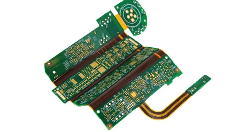
Rigid-flex PCBs are hybrid circuit boards that integrate rigid and flexible sections into a single design. They are widely used in industries like aerospace, medical devices, and consumer electronics, where space constraints and dynamic movement are common. The bend radius—the minimum radius a flexible section can bend without damage—is a key factor in ensuring the board’s longevity and functionality, especially in dynamic applications where the board undergoes repeated bending.
A poorly calculated bend radius can lead to mechanical stress, cracking of copper traces, or delamination of layers, ultimately causing failure. Understanding how to achieve the optimal bend radius is essential for maintaining signal integrity and structural durability. In the sections below, we’ll break down the process of rigid-flex PCB bend radius calculation and provide actionable insights for your designs.
Understanding Bend Radius in Flexible PCB Bending
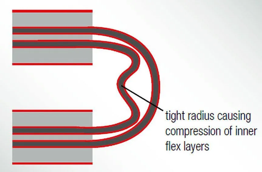
Bend radius refers to the tightest curve a flexible PCB section can endure without sustaining damage. For dynamic flex PCBs—those subjected to repeated bending during operation—the bend radius must be carefully calculated to prevent fatigue over time. A smaller bend radius increases stress on the materials, while a larger radius may not fit within the spatial constraints of the device.
The bend radius is influenced by several factors, including the thickness of the flexible section, the number of layers, and the type of materials used. For instance, a single-layer flex circuit can typically handle a tighter bend radius than a multilayer design due to reduced thickness and complexity. In dynamic applications, where bending occurs thousands or even millions of times, adhering to industry standards like IPC-2223 is crucial for reliability.
Rigid-Flex PCB Bend Radius Calculation: A Step-by-Step Guide
Calculating the bend radius for a rigid-flex PCB involves understanding the relationship between the board’s thickness and the desired bending performance. According to industry guidelines, the minimum bend radius is often expressed as a ratio of the bending radius (r) to the overall height or thickness (h) of the flexible section. This ratio varies depending on whether the application is static (bent once during assembly) or dynamic (repeated bending).
Here’s a simplified approach to rigid-flex PCB bend radius calculation:
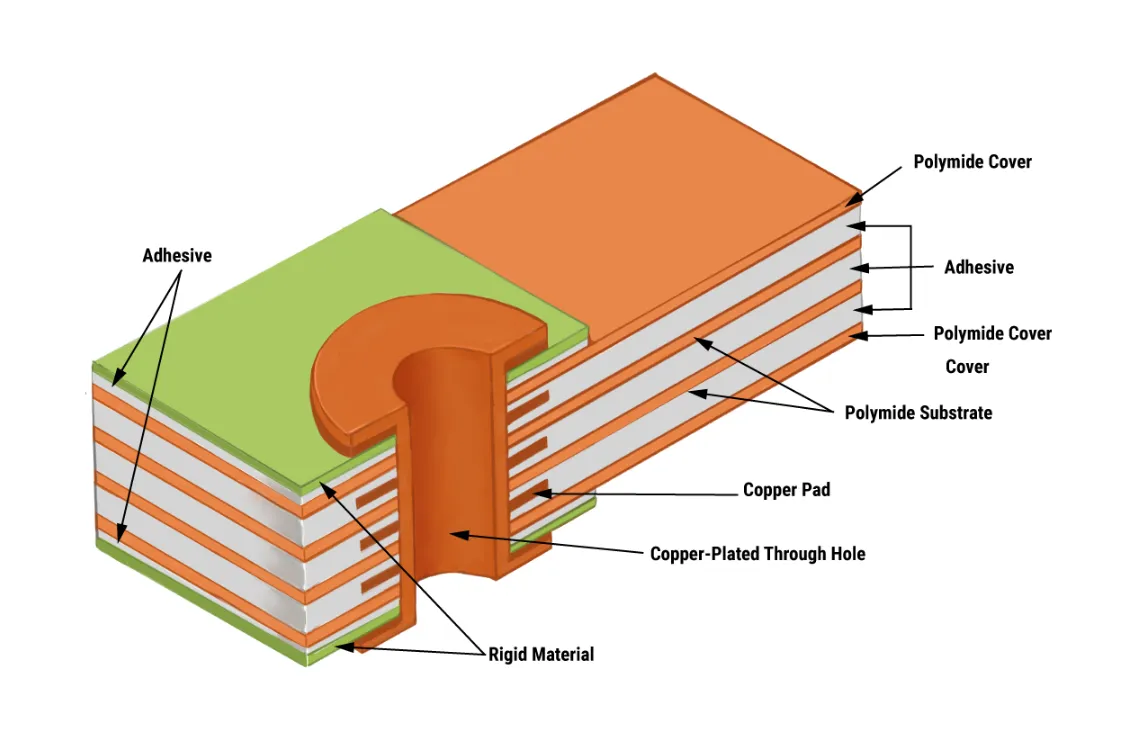
- Determine the Thickness (h): Measure the total thickness of the flexible section, including all layers such as substrate, copper, and adhesives. For example, a single-layer flex circuit might have a thickness of 0.09 mm (90 μm).
- Identify the Application Type: Decide if the flex PCB will be used in a static or dynamic application. Dynamic applications require a larger bend radius to reduce stress during repeated bending.
- Apply the Bend Radius Ratio: Refer to established ratios based on industry standards like IPC-2223. For a single-layer dynamic flex PCB, the minimum bend radius ratio is often 100:1. This means the bend radius (r) should be 100 times the thickness (h). Using our example, r = 100 x 0.09 mm = 9 mm.
- Adjust for Layers and Materials: For multilayer designs, the ratio increases. A double-layer dynamic flex might require a 150:1 ratio, while a static application could use a 10:1 ratio for a single layer.
This calculation provides a starting point, but real-world factors like material properties and environmental conditions may require adjustments. Testing prototypes under actual operating conditions is often necessary to validate the calculated bend radius.
IPC-2223 Bend Requirements: Industry Standards for Reliability
The IPC-2223 standard, developed by the Institute of Printed Circuits, provides detailed guidelines for designing flexible and rigid-flex PCBs. These standards are essential for ensuring that your design can withstand the mechanical and thermal stresses of bending. Here are some key IPC-2223 bend requirements to keep in mind for dynamic flex PCBs:
- Minimum Bend Radius Ratios: For dynamic applications, IPC-2223 recommends a minimum bend radius of 100:1 for single-layer flex circuits, 150:1 for double-layer, and up to 200:1 for multilayer designs. Static applications can use ratios as low as 10:1.
- Bend Area Design: Avoid placing vias, through-holes, or heavy components in the bend area, as they can create stress points and lead to cracking.
- Transition Zones: Ensure smooth transitions between rigid and flexible sections by using gradual curves and avoiding sharp edges that could tear the flexible material.
- Bend Cycles: For dynamic applications, IPC-2223 suggests testing the design for the expected number of bend cycles. A design intended for 100,000 cycles may require a larger bend radius than one for 1,000 cycles.
Following these guidelines helps ensure that your rigid-flex PCB can handle the mechanical demands of dynamic applications without compromising performance. Always consult the latest version of IPC-2223 during the design phase to stay compliant with industry best practices.
Material Selection for Bending: Choosing the Right Components
Material selection for bending is a critical factor in achieving the optimal bend radius for rigid-flex PCBs. The materials used in the flexible section must balance flexibility, durability, and electrical performance. Here are the key considerations when selecting materials for dynamic flex applications:
1. Substrate Materials
The substrate is the foundation of the flexible section, and its properties directly impact the bend radius. Common materials include:
- Polyimide: Known for its excellent thermal stability and flexibility, polyimide is the go-to choice for most flex PCBs. It can withstand temperatures up to 260°C and offers a low dielectric constant (around 3.5 at 1 MHz), making it ideal for high-frequency applications.
- Polyester: A more cost-effective option, polyester is suitable for less demanding applications but has lower thermal resistance (up to 150°C) and flexibility compared to polyimide.
For dynamic applications, polyimide is often preferred due to its ability to endure repeated bending without cracking. Thinner substrates (e.g., 25 μm or 50 μm) allow for tighter bend radii but may compromise mechanical strength.
2. Copper Foil Type
The copper foil used for conductive traces also affects bending performance. Rolled annealed (RA) copper is more flexible and resistant to fatigue than electrodeposited (ED) copper. RA copper can handle bend radii as tight as 10 times the foil thickness in static applications, while ED copper may crack under similar conditions. For dynamic flex PCBs, opt for RA copper with a thickness of 18 μm or 35 μm to balance conductivity and flexibility.
3. Adhesives and Coverlays
Adhesives bond the layers of a flex PCB, while coverlays protect the copper traces. Adhesive-less constructions are becoming popular for dynamic applications because they reduce thickness and improve flexibility. When adhesives are necessary, choose low-flow or no-flow options to minimize stress in the bend area. Coverlays should be made of flexible materials like polyimide to ensure they don’t restrict bending.
Design Tips for Dynamic Flex PCBs
Beyond calculating the bend radius and selecting materials, several design practices can enhance the performance of dynamic flex PCBs. These tips focus on minimizing stress and maximizing durability during repeated bending:
- Route Traces Strategically: Route copper traces perpendicular to the bend line to reduce stress. Avoid sharp corners in trace designs, as they can act as stress concentrators. Instead, use curved or teardrop-shaped transitions.
- Reinforce Bend Areas: Add PCB stiffeners or additional layers of material outside the bend area to provide support and prevent over-bending. Stiffeners can be made from polyimide or FR4 and should not extend into the flexible zone.
- Minimize Layer Count in Bend Zones: Reduce the number of layers in the flexible section to decrease thickness and allow for a tighter bend radius. For example, a 2-layer flex design will bend more easily than the 4-layer PCB.
- Test for Environmental Factors: Consider the operating environment, including temperature and humidity, as these can affect material properties. For instance, polyimide maintains flexibility at temperatures as low as -55°C, but extreme conditions may require additional testing.
By incorporating these design strategies, you can create a dynamic flex PCB that meets both mechanical and electrical requirements for your application.
Common Challenges in Achieving Optimal Bend Radius
Designing rigid-flex PCBs for dynamic applications comes with its share of challenges. Here are some common issues and how to address them:
- Material Fatigue: Repeated bending can cause fatigue in copper traces or substrates. Solution: Use a larger bend radius than the minimum recommended by IPC-2223 and opt for high-quality materials like RA copper.
- Space Constraints: Devices often require tight bend radii to fit within small enclosures. Solution: Use thinner materials and reduce layer counts in the flex area to achieve a smaller radius without sacrificing reliability.
- Signal Integrity Issues: Bending can affect impedance and signal speed, especially in high-frequency designs. Solution: Maintain consistent trace widths and spacing, and consider using materials with stable dielectric properties (e.g., polyimide with a dielectric constant of 3.5).
Addressing these challenges during the design phase can save time and costs by preventing failures in the field.
Why Partner with ALLPCB for Rigid-Flex PCB Manufacturing?
At ALLPCB, we specialize in manufacturing high-quality rigid-flex PCBs tailored for dynamic applications. Our advanced production capabilities and strict adherence to industry standards like IPC-2223 ensure that your designs achieve the optimal bend radius for reliability and performance. Whether you’re working on a compact wearable device or a complex aerospace system, our team provides end-to-end support from design consultation to final assembly.
We use state-of-the-art materials and precision manufacturing processes to deliver boards that meet the tightest bend radius requirements. With rigorous testing and quality control, we guarantee that your rigid-flex PCBs will withstand the demands of dynamic bending over their entire lifecycle.
Conclusion: Mastering Bend Radius for Dynamic Flex PCBs
Achieving the optimal bend radius for rigid-flex PCBs in dynamic applications requires a deep understanding of design principles, material properties, and industry standards like IPC-2223. By carefully calculating the bend radius, selecting the right materials for bending, and following best practices for flexible PCB design, you can ensure the durability and performance of your boards. Whether you’re tackling rigid-flex PCB bend radius calculation or navigating the challenges of dynamic flex PCB design, the insights provided in this guide offer a solid foundation for success.
With the right approach and a trusted manufacturing partner like ALLPCB, you can bring your innovative designs to life with confidence. Focus on precision, test thoroughly, and prioritize quality to create rigid-flex PCBs that meet the demands of today’s cutting-edge applications.


