 ALLPCB


In the world of printed circuit board (PCB) manufacturing, precision is everything. One critical factor that often determines the success of a PCB design is the aspect ratio in PCB drilling. But what exactly is aspect ratio, and why does it matter? Simply put, the aspect ratio is the relationship between the depth of a drilled hole and its diameter. A well-managed aspect ratio ensures reliable connections, prevents manufacturing defects, and maintains the integrity of the board. In this blog, we'll dive deep into the importance of aspect ratio in PCB drilling, explore techniques like CNC drilling and laser drilling, and address challenges such as drill bit wander and via misalignment. Whether you're an engineer or a designer, understanding these concepts will help you create high-quality PCBs with confidence.
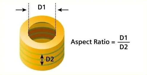
What Is Aspect Ratio in PCB Drilling?
Aspect ratio in PCB drilling refers to the ratio of the hole's depth to its diameter. For example, if a hole is 1.6 mm deep and has a diameter of 0.2 mm, the aspect ratio is 8:1. This measurement is crucial because it impacts how effectively a hole can be drilled and plated. High aspect ratios (like 10:1 or more) mean deeper, narrower holes, which are harder to drill accurately and plate with copper for conductivity. Low aspect ratios (like 3:1) are easier to manage but may not suit complex, high-density designs.
Why does this matter? In modern electronics, PCBs are shrinking in size while becoming more complex. High-density interconnect (HDI) designs often require microvias and small through-holes with high aspect ratios. If the aspect ratio isn't carefully considered, issues like incomplete plating, poor electrical connections, or even structural failures can occur. By understanding and optimizing the aspect ratio, manufacturers can ensure both precision and reliability in their boards.
Why Aspect Ratio Matters for Precision and Reliability
The aspect ratio directly affects the quality of vias and through-holes, which are essential for connecting different layers of a PCB. Here are some key reasons why it plays such a vital role:
- Drilling Accuracy: A high aspect ratio makes it harder for drill bits to stay centered, increasing the risk of drill bit wander. This can lead to misaligned holes that don't connect layers properly.
- Plating Challenges: During the plating process, copper must be deposited evenly inside the hole. With high aspect ratios, it's difficult for plating solutions to reach the bottom of deep, narrow holes, leading to weak or incomplete connections.
- Signal Integrity: Poorly drilled or plated holes can disrupt electrical signals, causing delays or losses. For high-speed designs, this can result in signal speeds dropping below required thresholds, such as failing to maintain 5 Gbps in certain applications.
- Structural Integrity: If holes are not drilled or plated correctly, the PCB may develop cracks or delamination over time, especially under thermal or mechanical stress.
Common PCB Drilling Techniques and Their Impact on Aspect Ratio
There are two primary methods for drilling holes in PCBs: CNC drilling and laser drilling. Each technique has its strengths and limitations when it comes to managing aspect ratio and achieving precision.
CNC Drilling: The Traditional Approach
CNC (Computer Numerical Control) drilling uses mechanical drill bits to create holes in a PCB. This method is widely used for through-holes and larger vias due to its cost-effectiveness and reliability for standard designs. However, CNC drilling struggles with high aspect ratios above 10:1. Here's why:
- Drill Bit Wander: As the drill bit goes deeper into the material, it can deviate from its intended path. This is especially common with small-diameter bits (below 0.3 mm) drilling deep holes, leading to via misalignment.
- Heat and Wear: Drilling generates heat and friction, which can wear out bits quickly, especially in high-aspect-ratio scenarios. Worn bits are more likely to produce uneven holes or break mid-process.
- Limits on Microvias: CNC drilling is less effective for microvias (holes smaller than 0.15 mm in diameter), which are common in HDI designs requiring high aspect ratios.
Despite these challenges, CNC drilling remains a go-to method for many applications. Manufacturers often mitigate issues by using high-quality drill bits, optimizing spindle speeds (e.g., 80,000 to 120,000 RPM), and carefully controlling entry and exit materials to reduce burrs and misalignment.
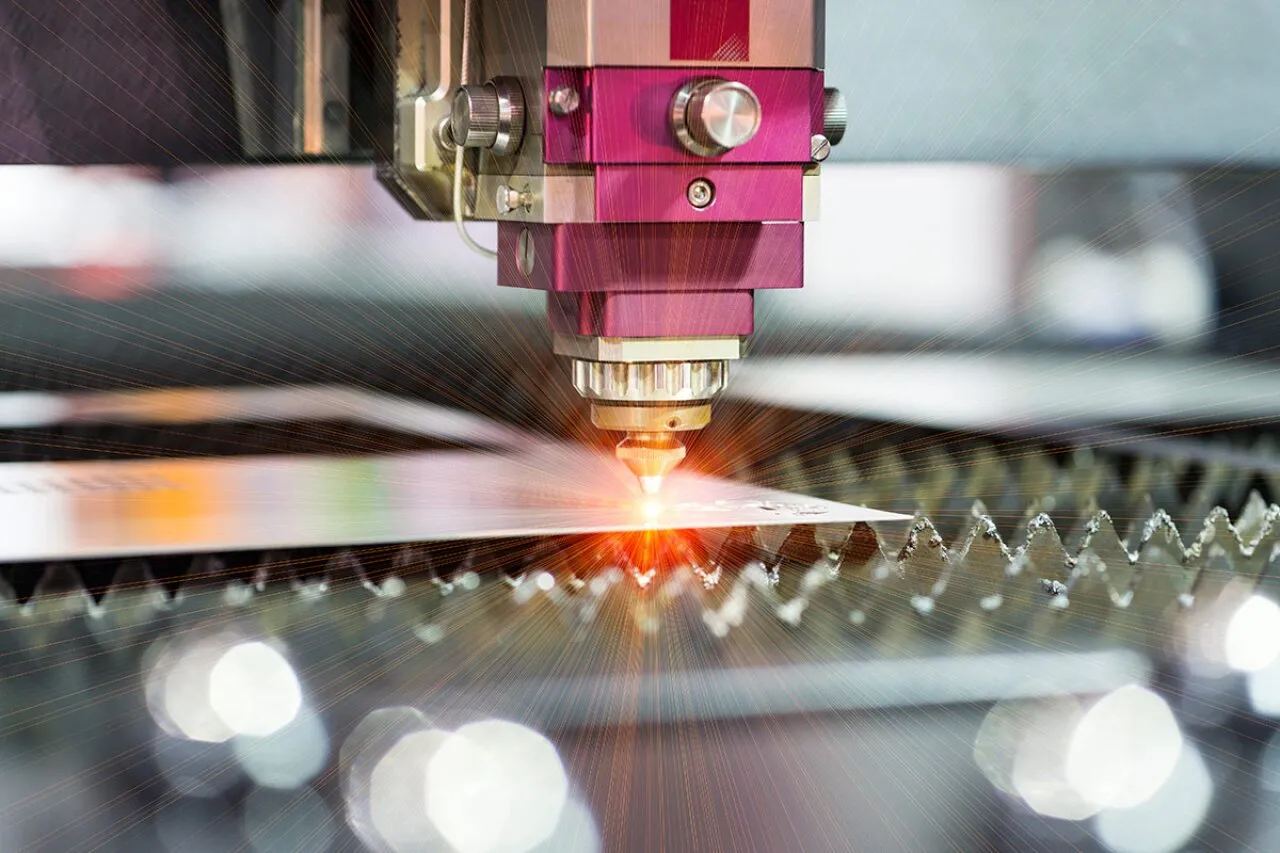
Laser Drilling: Precision for High Aspect Ratios
Laser drilling is a newer, more advanced technique that uses focused laser beams to create holes. It's particularly suited for microvias and high-aspect-ratio holes in HDI and advanced packaging designs. Here are some advantages and challenges:
- High Precision: Lasers can create holes as small as 0.025 mm with aspect ratios up to 20:1, far surpassing the capabilities of mechanical drills. This reduces the risk of drill bit wander and via misalignment.
- Non-Contact Process: Since there's no physical tool touching the material, there's no wear or heat buildup, ensuring consistent accuracy over long production runs.
- Limitations: Laser drilling is more expensive and slower for larger holes. It also struggles with thicker materials (above 1.6 mm) and may require additional cleaning to remove residue from the drilling process.
Laser drilling is often used in combination with CNC drilling to balance cost and precision. For example, larger through-holes might be drilled with CNC, while microvias are handled by lasers.
Challenges in PCB Drilling: Drill Bit Wander and Via Misalignment
Even with advanced drilling techniques, challenges like drill bit wander and via misalignment can compromise the quality of a PCB. Let's break down these issues and explore how they relate to aspect ratio.
Drill Bit Wander: A Common Problem in High Aspect Ratios
Drill bit wander occurs when a drill bit deviates from its intended path during drilling. This is more likely to happen with high aspect ratios because the bit must travel a greater depth relative to its diameter. Factors contributing to wander include:
- Bit Deflection: Small-diameter bits (e.g., 0.2 mm) are more flexible and can bend under pressure, especially in deeper holes.
- Material Inconsistencies: Variations in the PCB laminate or copper layers can cause the bit to shift off-course.
- Improper Setup: Incorrect spindle speed or feed rate (e.g., exceeding 150 mm/min for certain materials) can lead to instability during drilling.
The result of drill bit wander is often misaligned holes that fail to connect layers properly, leading to electrical failures. To minimize this, manufacturers use backup and entry materials to stabilize the board and advanced CNC machines with real-time monitoring to detect deviations.
Via Misalignment: A Risk to Connectivity
Via misalignment happens when drilled holes don't align with the intended pads or traces on different layers of the PCB. This can disrupt electrical connections and is often a direct result of drill bit wander or poor design-to-manufacturing alignment. High aspect ratios make misalignment more likely because even a slight deviation over a long depth can result in a significant offset at the bottom of the hole.
For instance, in a 12-layer PCB with a 1.6 mm thickness and 0.2 mm diameter vias (aspect ratio 8:1), a deviation of just 0.05 mm at the top can mean the via misses its target pad entirely at the bottom. This can cause open circuits or require costly rework. Solutions include using precise drilling equipment, implementing strict design rules (like maintaining a minimum annular ring of 0.1 mm), and thorough testing during production.
Best Practices for Optimizing Aspect Ratio in PCB Drilling
Achieving precision and reliability in PCB drilling starts with optimizing the aspect ratio and using the right techniques. Here are some actionable tips for engineers and designers:
- Design with Aspect Ratio in Mind: Aim for aspect ratios below 10:1 for standard designs to ensure manufacturability. For HDI designs requiring higher ratios, consult with your manufacturer early in the design phase to confirm capabilities.
- Choose the Right Drilling Method: Use CNC drilling for larger holes and standard designs, and reserve laser drilling for microvias and high-aspect-ratio holes in complex boards.
- Specify Tolerances: Clearly define tolerances for hole size and placement in your design files. For example, a tolerance of ±0.05 mm for hole diameter can help ensure consistency.
- Minimize Drill Bit Wander: Work with manufacturers who use high-quality bits, proper entry/exit materials, and optimized drilling parameters (e.g., spindle speeds of 100,000 RPM for small holes).
- Test and Inspect: Incorporate automated optical inspection (AOI) and electrical testing to catch issues like via misalignment before the board reaches assembly.
How Aspect Ratio Impacts Manufacturing Costs
Aspect ratio doesn't just affect quality—it also influences production costs. High aspect ratios often require specialized equipment, slower drilling speeds, and additional quality control measures, all of which drive up expenses. For example, drilling a hole with a 15:1 aspect ratio using laser technology can cost 20-30% more per hole than a 5:1 ratio drilled with CNC methods due to the precision and time required.
On the other hand, designing with lower aspect ratios can reduce costs by allowing faster production and fewer defects. Balancing performance needs with manufacturability is key to keeping projects within budget while maintaining reliability.
Future Trends in PCB Drilling and Aspect Ratio Management
As electronics continue to shrink and demand for HDI designs grows, managing aspect ratio in PCB drilling will become even more critical. Emerging trends include:
- Advanced Laser Systems: Newer laser drilling machines can handle even higher aspect ratios (up to 25:1) with improved speed and lower costs, making them more accessible for mainstream production.
- AI and Automation: Artificial intelligence is being integrated into drilling equipment to predict and correct issues like drill bit wander in real-time, improving precision.
- Material Innovations: New PCB materials with better thermal and mechanical properties are being developed to support high-aspect-ratio drilling without compromising board integrity.
Conclusion: Mastering Aspect Ratio for Better PCBs
The aspect ratio in PCB drilling is a small detail with a big impact. By understanding its role in precision and reliability, and by choosing the right drilling techniques—whether CNC drilling for standard applications or laser drilling for high-density designs—you can avoid common pitfalls like drill bit wander and via misalignment. Optimizing aspect ratio not only improves the quality of your PCBs but also streamlines manufacturing and reduces costs. As technology advances, staying informed about the latest drilling techniques and best practices will help you stay ahead in creating cutting-edge electronics. With careful planning and collaboration with your manufacturing partner, achieving flawless PCB designs is well within reach.


