 ALLPCB


If you're working on high-frequency printed circuit boards (PCBs), choosing the right solder mask material is critical to minimizing signal loss and ensuring top performance. So, what are the best solder mask materials for high-frequency PCBs? The answer lies in selecting materials with a low dielectric constant and low loss tangent to maintain signal integrity. In this comprehensive guide, we'll dive deep into the role of solder mask dielectric constant, the importance of low loss solder mask, and how to optimize high-frequency solder mask choices for better signal integrity. Let's explore how these factors impact your PCB design and performance.
What Is a Solder Mask and Why Does It Matter for High-Frequency PCBs?
A solder mask is a thin protective layer applied over the copper traces of a PCB. It prevents short circuits, protects against oxidation, and ensures solder only sticks to designated areas during assembly. While this layer is essential for any PCB, its impact on high-frequency designs is even more significant. At high frequencies, typically above 1 GHz, even small variations in materials can cause signal loss, distortion, or interference.
In high-frequency applications, such as 5G technology, radar systems, and high-speed digital circuits, signal integrity is everything. The solder mask can affect the electrical properties of the PCB, particularly through its dielectric constant (Dk) and dissipation factor (Df), also known as loss tangent. A poorly chosen solder mask can introduce unwanted signal delays or losses, degrading the performance of your design. This is why selecting a high-frequency solder mask with low loss properties is a top priority.
Understanding Solder Mask Dielectric Constant and Its Impact
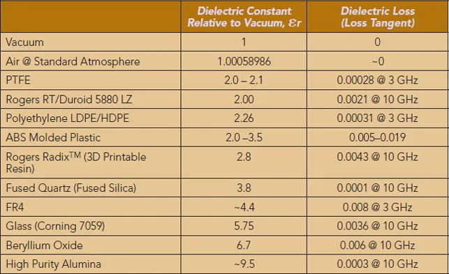
The dielectric constant (Dk) of a material measures how much it can store electrical energy in an electric field. For PCB materials, including solder masks, a lower Dk is generally better for high-frequency applications. Why? Because a high Dk can slow down signal propagation and increase the risk of signal distortion.
Standard solder masks often have a dielectric constant ranging from 3.5 to 4.5. While this is acceptable for low-frequency designs, it can cause issues in high-frequency circuits operating at 5 GHz or higher. At these frequencies, signals travel along the surface of the PCB, interacting closely with the solder mask. A high Dk can lead to impedance mismatches, resulting in signal reflections and loss. For comparison, specialized low-Dk solder masks can have values as low as 2.5 to 3.0, significantly reducing these effects.
For example, in a 10 GHz design, a solder mask with a Dk of 4.0 might cause a noticeable delay in signal propagation, while a low-Dk mask of 2.8 could improve timing accuracy by up to 10%. This difference can be critical in applications like telecommunications or automotive radar systems where precision matters.
Why Low Loss Solder Mask Is Essential for Signal Integrity
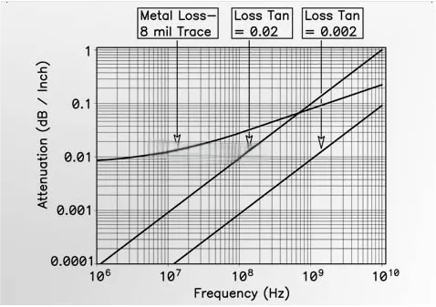
Beyond the dielectric constant, the dissipation factor (Df) or loss tangent of a solder mask plays a huge role in minimizing signal loss. The loss tangent indicates how much energy a material dissipates as heat when an electric field passes through it. A high Df means more signal energy is lost, which directly impacts signal integrity in high-frequency designs.
Standard solder masks often have a Df between 0.02 and 0.03, which is too high for many high-frequency applications. A low loss solder mask, with a Df below 0.01, can drastically reduce energy dissipation. For instance, in a high-speed digital circuit operating at 25 Gbps, using a low loss solder mask can reduce signal attenuation by as much as 20%, ensuring clearer and more reliable data transmission.
In short, a low loss solder mask is non-negotiable for maintaining signal integrity in high-frequency PCBs. It helps keep signals strong and reduces noise, which is vital for applications like wireless communication or satellite systems.
Types of Solder Mask Materials for High-Frequency PCBs
Not all solder masks are created equal, especially when it comes to high-frequency designs. Below are some common types of solder mask materials, along with their suitability for minimizing signal loss and maintaining signal integrity.
1. Epoxy-Based Solder Masks
Epoxy-based solder masks are the most common type used in PCB manufacturing. They are cost-effective and provide good protection against environmental factors. However, their dielectric constant typically ranges from 3.8 to 4.5, and their loss tangent is around 0.02, making them less ideal for high-frequency applications. These masks are better suited for low to mid-frequency designs where signal loss is not a major concern.
2. Polyimide-Based Solder Masks
Polyimide solder masks offer better performance for high-frequency PCBs. They have a lower dielectric constant, often around 3.2 to 3.5, and a reduced loss tangent of about 0.01. This makes them a solid choice for applications up to 10 GHz. Additionally, polyimide masks can withstand higher temperatures, which is beneficial for designs exposed to thermal stress.
3. Specialized Low-Dk/Low-Df Solder Masks
For the most demanding high-frequency applications, specialized solder masks with ultra-low dielectric constants (2.5 to 3.0) and loss tangents (below 0.005) are available. These materials are often used in cutting-edge technologies like 5G infrastructure and aerospace systems. While they are more expensive, the improvement in signal integrity can be worth the investment, especially when operating at frequencies above 20 GHz.
Design Tips for Using High-Frequency Solder Mask
Choosing the right solder mask material is only part of the equation. How you apply and integrate it into your PCB design also matters. Here are some practical tips to optimize your high-frequency solder mask for minimal signal loss and better signal integrity.
1. Minimize Solder Mask Coverage on Critical Traces
In high-frequency designs, it's often best to avoid applying solder mask over critical signal traces, especially RF lines. Exposed traces have less interaction with the mask's dielectric properties, reducing the risk of signal distortion. If protection is needed, consider using a very thin layer of low-Dk solder mask to balance protection and performance.
2. Match Impedance with Solder Mask Properties
Impedance control is vital for high-frequency signals. A mismatch between the PCB substrate and solder mask can cause signal reflections. For example, if your substrate has a Dk of 3.0, pair it with a solder mask of similar or lower Dk to maintain consistent impedance. Tools like impedance calculators can help you achieve a target impedance, often around 50 ohms for RF designs.
3. Test and Validate with Prototypes
Before mass production, create prototypes to test how your chosen solder mask affects signal integrity. Use tools like a vector network analyzer to measure signal loss and reflection at your target frequencies. This step can save time and money by identifying issues early.
Challenges with High-Frequency Solder Masks and How to Overcome Them
While low loss solder masks offer clear benefits, they come with challenges. First, they are often more expensive than standard options, which can impact project budgets. Second, some low-Dk materials may not adhere as well to certain substrates, leading to reliability issues over time.
To address cost concerns, prioritize low loss solder masks only for critical high-frequency areas of your PCB, using standard masks elsewhere. For adhesion issues, work closely with your PCB manufacturer to ensure compatibility between the solder mask and substrate materials. Thorough testing under real-world conditions can also help identify potential problems before they arise.
How Solder Mask Affects Signal Integrity in Real-World Applications
Let’s look at a practical example to illustrate the importance of signal integrity solder mask. In a 5G base station design operating at 28 GHz, signal loss must be kept below 0.5 dB per inch to meet performance standards. Using a standard epoxy solder mask with a Dk of 4.0 and Df of 0.025 could result in a loss of 0.8 dB per inch, failing to meet the requirement. Switching to a low loss solder mask with a Dk of 2.8 and Df of 0.005 can bring the loss down to 0.3 dB per inch, ensuring the design performs as expected.
This example shows how the right high-frequency solder mask can make or break a project. Whether you're designing for telecommunications, medical imaging, or automotive radar, paying attention to solder mask properties is a must.
Suggested Reading: Solder Mask Application: Best Practices for Durability
Future Trends in Solder Mask Materials for High-Frequency Designs
As technology advances, the demand for high-frequency PCBs will continue to grow. This means solder mask materials will need to evolve as well. Researchers are working on new formulations with even lower dielectric constants and loss tangents, potentially reaching Dk values below 2.0. Additionally, environmentally friendly solder masks with high-frequency performance are gaining traction, aligning with global sustainability goals.
Another trend is the integration of solder masks with advanced manufacturing techniques like additive processes. These methods could allow for more precise application of solder masks, reducing their impact on critical signal paths. Staying updated on these developments can give designers a competitive edge in creating cutting-edge high-frequency PCBs.
Conclusion: Choosing the Right Solder Mask for Your High-Frequency PCB
When it comes to high-frequency PCBs, the solder mask is far more than just a protective layer. Its dielectric constant, loss tangent, and overall material properties directly influence signal loss and signal integrity. By prioritizing a high-frequency solder mask with low loss characteristics, such as those with a Dk below 3.0 and Df below 0.01, you can significantly improve the performance of your design.
Remember to consider your specific application needs, test different materials, and optimize your design to balance cost and performance. With the right low loss solder mask and careful planning, you can minimize signal loss and achieve reliable, high-quality results in even the most demanding high-frequency projects. At ALLPCB, we're here to support you with expert guidance and top-notch manufacturing solutions for all your PCB needs.


