ALLPCB


If you're dealing with engine performance issues in your vehicle, a faulty Engine Control Unit (ECU) Printed Circuit Board (PCB) might be the culprit. In this comprehensive guide, we'll dive into ECU PCB fault diagnosis, engine control unit PCB repair, and troubleshooting automotive PCBs. We'll also cover ECU PCB testing procedures and highlight common ECU PCB failures to help you identify and resolve issues effectively. Whether you're an automotive technician or a DIY enthusiast, this blog will provide actionable insights to get your vehicle back on track.
What is an Engine Control Unit PCB and Why Does it Matter?
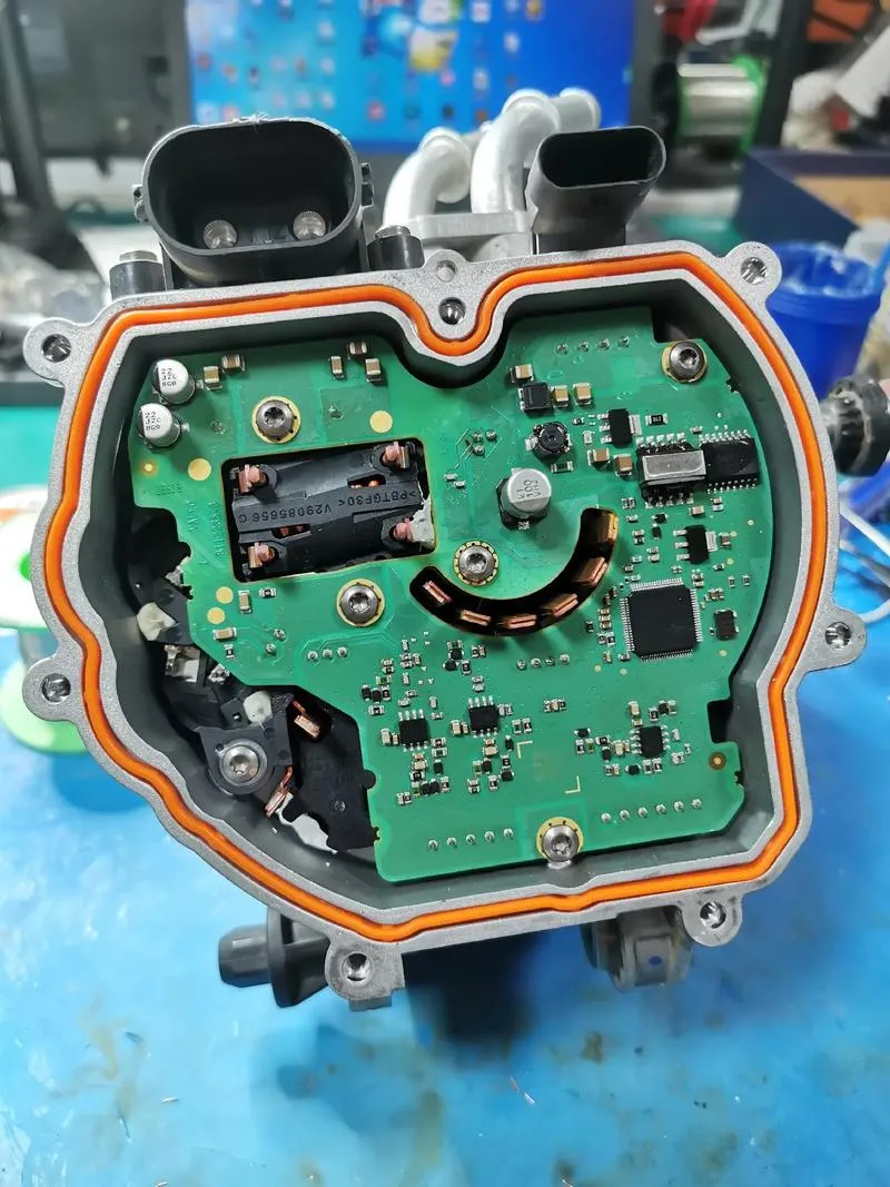
The Engine Control Unit (ECU) is the brain of a modern vehicle, controlling critical functions like fuel injection, ignition timing, and emission systems. At the heart of the ECU lies the Printed Circuit Board (PCB), a complex network of electronic components and traces that process signals and execute commands. When the ECU PCB develops issues, it can lead to poor engine performance, increased emissions, or even complete vehicle failure.
Understanding how to troubleshoot and repair these boards is essential for maintaining vehicle reliability. A small fault, like a broken solder joint or a burned-out capacitor, can disrupt the entire system. In this post, we'll walk you through the most common problems and solutions to keep your ECU functioning smoothly.
Common ECU PCB Failures to Watch For
Before diving into troubleshooting, it's important to recognize the typical issues that plague ECU PCBs. Here are some of the most frequent failures encountered in automotive electronics:
- Corrosion and Moisture Damage: Exposure to humidity or water ingress can corrode PCB traces and components, leading to short circuits or signal loss. This is common in vehicles operated in wet or humid climates.
- Solder Joint Cracks: Vibration and thermal cycling in a vehicle can cause solder joints to crack over time, interrupting connections between components and the board.
- Component Burnout: Capacitors, resistors, and transistors can fail due to voltage spikes or overheating, often caused by electrical surges or poor heat dissipation.
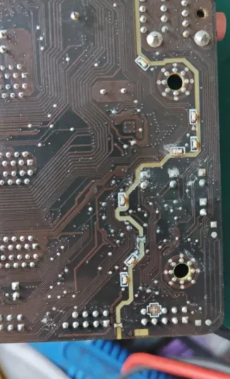
- Trace Damage: Physical stress or manufacturing defects can lead to broken or damaged traces on the PCB, disrupting the flow of electrical signals.
- Software or Firmware Issues: While not directly a hardware fault, corrupted firmware can mimic PCB failure by causing erratic behavior in the ECU.
These failures often manifest as symptoms like engine misfires, stalling, poor fuel efficiency, or diagnostic trouble codes (DTCs) appearing on a scan tool. Identifying the root cause is the first step in effective ECU PCB fault diagnosis.
Step-by-Step ECU PCB Testing Procedures
Testing an ECU PCB requires a systematic approach to pinpoint faults accurately. Below are detailed ECU PCB testing procedures to guide you through the process:
1. Visual Inspection
Start with a thorough visual check of the PCB. Use a magnifying glass or microscope to look for signs of corrosion, burnt components, or cracked solder joints. Pay close attention to areas near connectors and heat sinks, as these are prone to damage.
2. Power Supply Check
Measure the input voltage to the ECU using a multimeter. Most automotive ECUs operate on a 12V supply, but this can vary. Ensure the voltage is within the manufacturer’s specified range (typically 11.5V to 14.5V during operation). A deviation could indicate a power supply issue affecting the PCB.
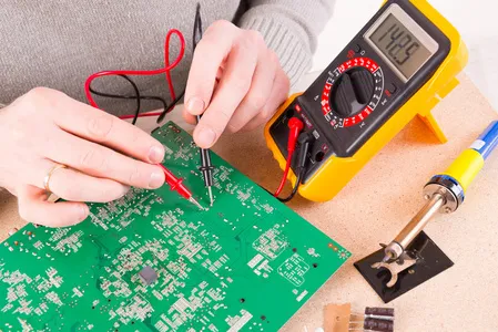
3. Continuity Testing
Use a multimeter in continuity mode to test for broken traces or open circuits on the PCB. Focus on critical paths, such as those leading to the microcontroller or sensor inputs. A reading of infinite resistance indicates a break that needs repair.
4. Component Testing
Test individual components like capacitors, resistors, and diodes for proper function. For instance, a capacitor rated at 10μF should show a capacitance close to this value when tested with a capacitance meter. Replace any component that shows values outside the acceptable range (typically ±10% of the rated value).
5. Signal Testing
With the ECU powered on, use an oscilloscope to monitor signal integrity at key points, such as sensor inputs and actuator outputs. For example, a crankshaft position sensor signal should show a consistent square wave with a frequency proportional to engine RPM (e.g., 500 Hz at 3000 RPM for some engines). Irregular waveforms or noise indicate a potential PCB issue.
Troubleshooting Automotive PCBs: Practical Tips
Troubleshooting automotive PCBs can be challenging due to the harsh operating environment of vehicles. Here are some practical tips to streamline the process and avoid common pitfalls:
- Use Diagnostic Tools: Invest in a reliable OBD-II scanner to read error codes from the ECU. Codes like P0606 (ECU/PCM Processor Fault) often point to internal PCB issues.
- Check Ground Connections: Poor grounding can cause erratic ECU behavior. Ensure all ground points are clean and secure, with resistance to chassis ground below 0.1 ohms.
- Avoid Static Damage: Always wear an anti-static wrist strap when handling PCBs to prevent electrostatic discharge (ESD), which can damage sensitive components like microcontrollers.
- Document Everything: Take photos of the PCB before disassembly and note the location of each connector and screw. This helps during reassembly and ensures no steps are missed.
- Test in Controlled Conditions: If possible, use a bench setup with a stable power supply (e.g., 12V DC at 5A) to test the ECU outside the vehicle. This isolates external factors like wiring issues.
By following these tips, you can reduce diagnostic errors and improve the efficiency of your troubleshooting process.
Engine Control Unit PCB Repair Techniques
Once you've identified the issue, the next step is engine control unit PCB repair. Here are some common repair techniques tailored for ECU PCBs:
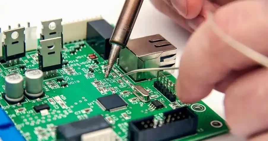
1. Soldering Fixes
For cracked solder joints, use a soldering iron with a fine tip (e.g., 25W with a 1mm tip) and high-quality solder (60/40 tin-lead or lead-free). Heat the joint for 2-3 seconds, apply fresh solder, and ensure a shiny, smooth finish. Avoid excessive heat, as it can damage nearby components.
2. Component Replacement
Replace faulty components like capacitors or resistors with parts matching the original specifications. For example, if replacing a 220μF capacitor rated at 16V, ensure the replacement matches these values to prevent circuit imbalance.
3. Trace Repair
For broken traces, use a conductive pen or thin wire to bridge the gap. Apply a small amount of solder to secure the connection, then cover with insulating tape or conformal coating to prevent short circuits.
4. Cleaning Corrosion
If corrosion is present, clean the affected area with isopropyl alcohol (90% or higher) and a soft brush. Dry thoroughly with compressed air, then apply a protective coating to prevent future corrosion.
5. Firmware Update or Reprogramming
If the issue is software-related, use a compatible programming tool to update or reflash the ECU firmware. Ensure you have the correct software version for your vehicle model to avoid compatibility issues.
Preventing Common ECU PCB Failures
While repairs are essential, preventing issues in the first place can save time and money. Here are some strategies to protect your ECU PCB from common ECU PCB failures:
- Seal Against Moisture: Ensure the ECU housing is properly sealed to prevent water ingress. Use silicone sealant around gaskets if necessary.
- Manage Heat: Avoid placing the ECU near heat sources like the engine block. If possible, add a heat shield or improve ventilation around the unit.
- Protect Against Voltage Spikes: Install a surge protector or voltage regulator in the vehicle’s electrical system to prevent spikes above 15V, which can damage PCB components.
- Regular Inspections: Periodically check the ECU for signs of wear or damage, especially after driving in harsh conditions like off-road or extreme weather.
When to Seek Professional Help
While many ECU PCB issues can be resolved with the right tools and knowledge, some cases require professional expertise. If the PCB has extensive damage, such as multiple burnt components or a failed microcontroller, it may be more cost-effective to replace the unit or consult a specialist. Additionally, if you're unable to reprogram the firmware or lack advanced diagnostic equipment like a logic analyzer, a professional service can provide the necessary support.
Conclusion
Troubleshooting and repairing an Engine Control Unit PCB can seem daunting, but with the right approach, it's a manageable task. By understanding common ECU PCB failures, following systematic ECU PCB testing procedures, and applying effective engine control unit PCB repair techniques, you can restore your vehicle's performance and reliability. Whether you're tackling ECU PCB fault diagnosis or troubleshooting automotive PCBs, the key is patience and precision.
Armed with the insights from this guide, you're better equipped to handle ECU PCB issues and keep your vehicle running smoothly. Remember to use proper tools, take safety precautions, and prioritize prevention to avoid future problems. If you're looking for high-quality PCB solutions or support for automotive applications, our team is here to help with reliable services and expertise.