 ALLPCB


If you're diving into 4 oz copper PCB prototyping, you're likely working on a project that demands high current capacity or exceptional thermal management. How can you ensure success with such a specialized material? The key lies in understanding the unique properties of 4 oz copper, selecting the right design practices, and partnering with a reliable service for PCB quick turn and PCB prototype assembly. In this comprehensive guide, we'll walk you through actionable tips and tricks to make your prototyping process smooth and effective.
Why Choose 4 oz Copper for PCB Prototyping?
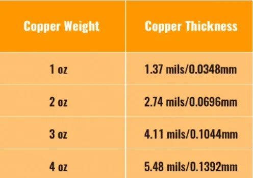
When it comes to PCB design, copper thickness plays a critical role in performance. Measured in ounces per square foot, copper weight determines how much current a board can handle and how well it dissipates heat. A standard PCB often uses 1 oz or 2 oz copper, which translates to a thickness of about 1.4 mils (0.0014 inches) and 2.8 mils (0.0028 inches), respectively. In contrast, 4 oz copper is significantly thicker at around 5.6 mils (0.0056 inches), making it ideal for specific applications.
So, why opt for 4 oz copper in your prototyping? This heavier copper weight is perfect for high-power circuits, such as those found in industrial equipment, automotive systems, and power supplies. It can carry currents upwards of 20-30 amps on a single trace (depending on width and temperature), compared to just 5-10 amps for 1 oz copper under similar conditions. Additionally, its enhanced thermal conductivity helps manage heat in high-performance designs, reducing the risk of component failure.
Challenges of Working with 4 oz Copper in PCB Prototyping
While 4 oz copper offers impressive benefits, it also introduces unique challenges during the prototyping phase. Understanding these hurdles upfront can save you time and resources during your PCB quick turn process.
- Increased Manufacturing Complexity: The thicker copper requires more precise etching and drilling processes. This can lead to longer fabrication times if not handled by an experienced manufacturer.
- Higher Costs: Due to the increased material and processing demands, 4 oz copper PCBs are generally more expensive than their thinner counterparts.
- Design Limitations: Thicker copper can affect trace spacing and impedance. For instance, achieving a 50-ohm impedance for RF signals may require wider traces or adjusted dielectric materials, complicating high-frequency designs.
- Weight and Flexibility: The added copper weight makes the board heavier and less flexible, which might be a concern for certain compact or lightweight applications.
Despite these challenges, with the right approach, you can navigate the prototyping process effectively and achieve outstanding results.
Top Tips for Successful 4 oz Copper PCB Prototyping
Now that you understand the benefits and challenges, let’s dive into practical strategies to ensure success with 4 oz copper PCB prototyping. These tips are designed to help engineers and designers optimize their process from design to assembly.
1. Optimize Your PCB Design for 4 oz Copper
Designing for 4 oz copper requires careful consideration of trace width, spacing, and layer stackup. Since thicker copper carries more current, you can use narrower traces for the same current load compared to 1 oz copper. However, ensure that your trace widths comply with thermal and current-carrying requirements. For example, a 0.5-inch wide trace with 4 oz copper can handle approximately 25 amps at a 30°C temperature rise, but always use a trace width calculator to confirm your specific needs.
Additionally, maintain adequate spacing between traces to prevent short circuits, especially since thicker copper can result in deeper etching profiles. A minimum spacing of 10-12 mils is often recommended for 4 oz copper, compared to 6-8 mils for 1 oz, depending on the manufacturer’s capabilities.
Lastly, consider your layer stackup. If your design includes multiple layers, ensure the inner layers (if using thinner copper) can handle the current and thermal load, or opt for 4 oz copper across all layers for consistency.
2. Focus on Thermal Management
One of the primary reasons for using 4 oz copper is its superior heat dissipation. However, you still need to design with thermal management in mind. Place thermal vias strategically around high-power components to transfer heat from the top layer to the bottom or internal layers. A grid of vias with a diameter of 12 mils and a spacing of 50 mils can significantly improve heat dissipation.
Also, consider adding copper pours or planes connected to ground or power nets. These large copper areas act as heat sinks, distributing thermal energy across the board and preventing hotspots. Ensure that these pours are well-connected to the thicker 4 oz copper layers for maximum effect.
3. Select the Right Materials and Finishes
The choice of substrate material and surface finish can impact the performance of your 4 oz copper PCB. For high-current applications, opt for a high-Tg (glass transition temperature) FR-4 material or advanced laminates like polyimide, which can withstand temperatures above 150°C without degrading.
For surface finishes, ENIG (Electroless Nickel Immersion Gold) is often a good choice for 4 oz copper boards due to its durability and excellent solderability. However, if cost is a concern, HASL (Hot Air Solder Leveling) can also work for prototyping, though it may not provide as smooth a finish on thicker copper.
4. Partner with a Reliable PCB Quick Turn Service
Prototyping with 4 oz copper demands precision and expertise, especially during the PCB quick turn process. Working with a manufacturer that specializes in heavy copper boards ensures that your design is fabricated accurately. Look for a service that offers rapid turnaround times without compromising on quality, ideally delivering bare boards within 24-48 hours for urgent projects.
Before submitting your design, double-check the manufacturer’s design rules for 4 oz copper, as they may have specific requirements for trace width, spacing, and drill sizes. Clear communication with the fabrication team can prevent delays and ensure your prototype meets expectations.
5. Streamline PCB Prototype Assembly for Heavy Copper
During PCB prototype assembly, handling 4 oz copper boards requires extra care. The thicker copper can affect soldering processes due to its higher thermal mass, meaning it takes longer to heat up and cool down. Ensure that your assembly process uses reflow profiles adjusted for heavy copper, with peak temperatures around 245-260°C for lead-free solder to avoid cold joints.
Also, verify that components are rated for the high currents and temperatures associated with 4 oz copper designs. For instance, use power resistors and capacitors with appropriate voltage and current ratings, and consider surface-mount components with larger pads to accommodate the thicker copper.
6. Test and Validate Your Prototype Thoroughly
Once your 4 oz copper PCB prototype is assembled, rigorous testing is essential to confirm its performance. Use a multimeter to check for continuity and resistance across high-current traces, ensuring they match your design calculations. For thermal performance, employ an infrared camera to identify hotspots, especially around power components, and verify that temperatures remain within safe limits (typically below 85°C for most components).
If your design involves high-frequency signals, test for signal integrity using an oscilloscope to measure impedance and signal loss. A mismatch in impedance (e.g., deviating from a target of 50 ohms) can cause reflections and degrade performance, so adjust trace widths or dielectric materials if needed.

Common Mistakes to Avoid in 4 oz Copper PCB Prototyping
Even with the best intentions, mistakes can happen during prototyping. Here are some pitfalls to watch out for when working with 4 oz copper:
- Underestimating Current Needs: Failing to calculate the correct trace width for high currents can lead to overheating or trace failure. Always use a reliable current-carrying capacity chart or calculator.
- Ignoring Manufacturer Guidelines: Not adhering to fabrication rules for 4 oz copper can result in rejected designs or poor-quality boards. Review the design rules before submission.
- Skipping Thermal Analysis: Neglecting to simulate or test thermal performance can cause components to overheat, reducing the lifespan of your PCB.
- Overlooking Assembly Challenges: Not adjusting soldering profiles for heavy copper can lead to poor solder joints, impacting reliability.
Benefits of Mastering 4 oz Copper Prototyping
Successfully prototyping with 4 oz copper opens up new possibilities for your projects. You’ll be able to create robust designs capable of handling high currents and extreme conditions, giving you a competitive edge in industries like automotive, renewable energy, and industrial automation. Plus, by optimizing your design and partnering with a trusted PCB quick turn service, you can reduce time-to-market and iterate faster during the development phase.
Mastering the assembly process through PCB prototype assembly services ensures that your heavy copper boards are built to perform, even under demanding conditions. The upfront effort in learning these techniques pays off with reliable, high-quality prototypes that meet your project goals.
Conclusion
Prototyping with 4 oz copper offers unmatched advantages for high-power and high-thermal applications, but it requires careful planning and execution. By optimizing your design, focusing on thermal management, selecting the right materials, and partnering with a dependable manufacturer for PCB quick turn and PCB prototype assembly, you can overcome the challenges of 4 oz copper PCB prototyping. Follow the tips and tricks outlined in this guide to ensure your next prototype is a success, delivering the performance and reliability your project demands.
With these strategies in hand, you’re well-equipped to tackle the unique demands of heavy copper prototyping and bring your innovative designs to life.


