 ALLPCB


If you're looking to understand semi rigid-flex PCBs and how they can benefit your projects, you've come to the right place. In simple terms, a semi rigid-flex PCB combines the stability of rigid circuit boards with the adaptability of flexible circuits, offering a unique solution for compact and reliable designs. This guide will dive deep into what semi rigid-flex PCBs are, their advantages, design tips, and how they compare to options like wire harnesses and conventional wire designs. Whether you're an engineer or a designer, you'll find practical insights to help you make informed decisions for your next project.
What Is a Semi Rigid-Flex PCB?
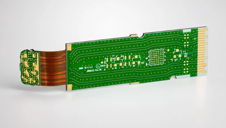
A semi rigid-flex PCB, often referred to as a semiflex PCB, is a hybrid circuit board that integrates both rigid and flexible sections into a single design. Unlike fully rigid PCBs, which are stiff and unbendable, or fully flexible PCBs, which can bend freely, semi rigid-flex boards offer a balance. The rigid parts provide structural support for mounting components like connectors and chips, while the flexible sections allow the board to bend or fold in specific areas, saving space and reducing the need for additional wiring.
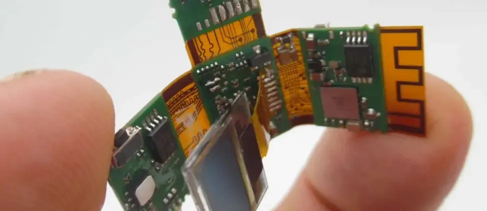
This type of PCB is ideal for applications where space is limited, and reliability is critical. Think of devices like medical equipment, aerospace systems, or compact consumer electronics. By combining rigidity and flexibility, these boards can fit into tight enclosures while maintaining strong electrical connections.
Key Benefits of Semi Rigid-Flex PCBs
Semi rigid-flex PCBs offer several advantages that make them a popular choice for modern electronics. Here are some of the standout benefits:
- Space Efficiency: The flexible portions allow the board to fold or bend, fitting into smaller spaces compared to traditional rigid boards. This can reduce the overall size of a device by up to 30% in some designs.
- Reduced Weight: By eliminating the need for bulky connectors and wire harnesses, semi rigid-flex PCBs can lower the weight of a product, which is crucial in industries like aerospace where every gram counts.
- Improved Reliability: With fewer connectors and soldered joints, there are fewer points of failure. This can enhance the durability of the device, especially in high-vibration environments.
- Cost-Effective in the Long Run: Although initial design and manufacturing costs might be higher, the reduction in assembly time and fewer components can save money over time.
- Simplified Assembly: Integrating rigid and flexible sections into one board means less manual assembly of wires or harnesses, streamlining production.
Applications of Semi Rigid-Flex PCBs
The unique properties of semi rigid-flex PCBs make them suitable for a wide range of industries. Here are some common applications:
- Medical Devices: Compact designs in wearable health monitors or imaging equipment benefit from the space-saving and lightweight nature of these boards.
- Aerospace and Defense: High reliability and reduced weight are essential for satellites, drones, and military hardware.
- Consumer Electronics: Smartphones, cameras, and other portable devices use semi rigid-flex PCBs to fit complex circuits into tiny spaces.
- Automotive Systems: These boards withstand vibrations and temperature changes, making them ideal for sensors and control units in vehicles.
Designing a Semi Rigid-Flex PCB: Key Considerations
Designing a semi rigid-flex PCB, or a design semi-rigid board, requires careful planning to ensure functionality and reliability. Here are some critical factors to keep in mind:
1. Define Rigid and Flexible Areas
Start by identifying which parts of your circuit need to be rigid and which need to be flexible. Rigid areas should house heavy components like connectors and ICs, while flexible sections are best for lightweight traces or areas that need to bend. For example, if you're designing a wearable device, the rigid section might hold the main processor, while the flexible part wraps around a wristband.
2. Material Selection
The materials used in semi rigid-flex PCBs are crucial for performance. Flexible areas often use polyimide, a durable and heat-resistant material, while rigid sections might use FR4, a common fiberglass laminate. Ensure the materials can handle the expected bending radius—typically, a minimum bend radius of 6 times the thickness of the flexible layer is recommended to avoid cracking.
3. Bend Radius and Stress Points
Avoid sharp bends or tight curves in the flexible areas, as they can create stress points that lead to fractures over time. A gradual bend with a radius of at least 1.5mm is often suggested for most designs. Also, avoid placing vias or critical traces near bend areas to minimize the risk of damage.
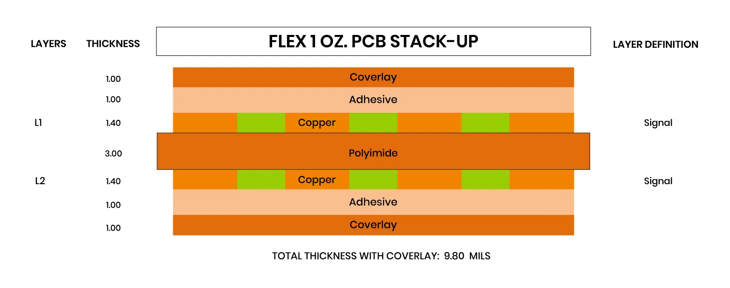
4. Layer Stack-Up
Plan your layer stack-up carefully. Semi rigid-flex designs often have multiple layers, with rigid sections having more layers for complex routing and flexible sections having fewer to maintain flexibility. A typical design might have 4 layers in the rigid area and 2 in the flexible zone. Ensure proper alignment between layers to avoid signal integrity issues, especially if high-speed signals (e.g., 1 GHz or higher) are involved.
5. Component Placement
Place high-density or heavy components only on rigid sections to prevent stress on flexible areas. For instance, a surface-mount connector weighing 5 grams or more should be mounted on a rigid zone to avoid bending issues.
Semi Rigid-Flex PCB vs. Wire Harnesses Design
Before the rise of flexible and semi rigid-flex PCBs, wire harnesses were the go-to solution for connecting components in complex systems. However, semi rigid-flex designs offer several advantages over traditional wire harnesses design:
- Space and Weight: Wire harnesses are bulky and heavy, often taking up 20-30% more space than a semi rigid-flex PCB. In contrast, the integrated design of a semi rigid-flex board eliminates the need for extra cables.
- Reliability: Wire harnesses have multiple connection points that can loosen or fail under vibration. A semi rigid-flex PCB reduces these points, improving reliability by up to 40% in high-stress environments.
- Assembly Time: Assembling a wire harness can take hours of manual labor, while a semi rigid-flex PCB simplifies the process, potentially cutting assembly time by half.
That said, wire harnesses may still be preferable for applications requiring frequent disconnection or very long cable runs, where flexibility beyond the capability of a PCB is needed.
Semi Rigid-Flex PCB vs. Conventional Wire Design
Conventional wire design, which often involves point-to-point wiring with individual wires and connectors, is another older method that semi rigid-flex PCBs can replace in many cases. Here's how they compare:
- Complexity: Conventional wire design can become messy and error-prone in dense systems, with a higher chance of miswiring. A semi rigid-flex PCB integrates connections into a single board, reducing complexity.
- Signal Integrity: Loose wires in conventional designs can introduce noise or crosstalk, especially at signal speeds above 100 MHz. Semi rigid-flex PCBs offer controlled impedance (e.g., 50 ohms for many high-speed designs), ensuring better signal quality.
- Durability: Wires can fray or break over time, while the flexible sections of a semi rigid-flex PCB are designed to withstand repeated bending—often up to 100,000 cycles in well-designed boards.
However, conventional wire design might still be useful for very low-cost, simple projects where signal speed and space aren't concerns.
Challenges in Semi Rigid-Flex PCB Design
While semi rigid-flex PCBs offer many benefits, they come with unique challenges that designers must address:
- Higher Initial Cost: The manufacturing process for semi rigid-flex PCBs is more complex than for standard rigid boards, often increasing costs by 20-50% upfront.
- Design Complexity: Designers need specialized software and expertise to handle the transition between rigid and flexible areas, which can add to development time.
- Testing Limitations: Unlike rigid boards, semi rigid-flex PCBs can be harder to test due to their shape and bending requirements, sometimes requiring custom test fixtures.
Tips for Optimizing Your Semi Rigid-Flex PCB Design
To ensure a successful design semi-rigid board project, follow these practical tips:
- Collaborate Early with Manufacturers: Work with your PCB fabrication team during the design phase to understand their capabilities and limitations, especially regarding material choices and minimum bend radii.
- Use Simulation Tools: Simulate bending and stress points using design software to predict potential failures before production. This can save costly redesigns.
- Minimize Layer Transitions: Keep transitions between rigid and flexible layers as smooth as possible to avoid delamination, a common issue in poorly designed boards.
- Test Prototypes Thoroughly: Build and test multiple prototypes under real-world conditions, such as temperature ranges from -40°C to 85°C, to ensure reliability.
Why Choose Semi Rigid-Flex PCBs for Your Next Project?
Semi rigid-flex PCBs are a game-changer for engineers and designers looking to create compact, reliable, and innovative products. By integrating the best of rigid and flexible technologies, they reduce weight, save space, and improve performance compared to traditional solutions like wire harnesses design or conventional wire design. Whether you're working on a cutting-edge medical device or a high-performance automotive system, these boards can help you achieve your goals.
At ALLPCB, we’re committed to supporting your projects with high-quality manufacturing solutions tailored to your needs. From initial design to final production, our expertise ensures that your semi rigid-flex PCB meets the highest standards of performance and reliability.
Conclusion
Semi rigid-flex PCBs represent a powerful solution for modern electronics, blending the stability of rigid boards with the versatility of flexible circuits. By understanding their benefits, applications, and design considerations, you can leverage this technology to create better products. Whether you're replacing outdated wire harnesses or optimizing a compact design, a well-planned semi rigid-flex PCB can make all the difference. Use the tips and insights from this guide to start your next project with confidence, knowing you have the knowledge to design a semi-rigid board that meets your needs.


