 ALLPCB


If you're facing challenges with a pacemaker PCB, you're likely searching for reliable ways to identify and fix issues like failure modes, component breakdowns, or circuit malfunctions. This comprehensive guide offers a step-by-step approach to troubleshooting medical PCBs, focusing on pacemaker PCB repair techniques, component failure analysis in pacemakers, and debugging pacemaker PCB circuits. Whether you're an engineer or a technician, this resource will help you resolve common problems efficiently.
In the detailed sections below, we'll dive into the intricacies of pacemaker PCB failure modes, explore practical troubleshooting methods, and provide actionable tips to ensure the reliability of these life-critical devices. Let's get started on understanding and fixing the issues that can affect pacemaker performance.
Understanding Pacemaker PCBs: Why Troubleshooting Matters
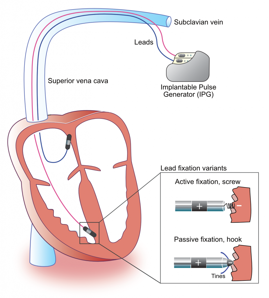
Pacemaker printed circuit boards (PCBs) are the heart of implantable medical devices that regulate a patient's heartbeat. These compact, highly specialized boards must operate flawlessly under strict conditions, as even minor failures can have life-threatening consequences. Troubleshooting medical PCBs, especially for pacemakers, requires precision, technical expertise, and an understanding of the unique challenges these devices face, such as biocompatibility, power constraints, and electromagnetic interference (EMI).
In this guide, we'll cover the most common pacemaker PCB failure modes and provide a structured approach to debugging and repair. Our goal is to equip you with the knowledge to maintain the functionality of these critical components, ensuring patient safety and device reliability.
Common Pacemaker PCB Failure Modes
Before diving into troubleshooting techniques, it's essential to understand the typical failure modes that affect pacemaker PCBs. Identifying the root cause of a problem is the first step in effective repair. Here are the most frequent issues encountered:
- Component Degradation: Over time, components like capacitors and resistors can degrade due to thermal stress or aging. For instance, electrolytic capacitors may leak or lose capacitance, leading to unstable voltage levels (e.g., dropping from a required 3.3V to below 2.8V).
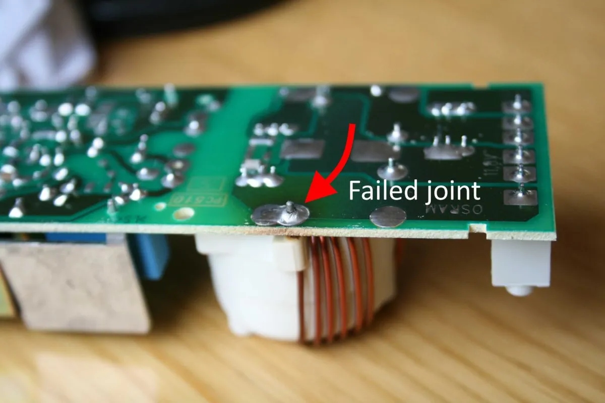
- Solder Joint Failures: Vibrations or mechanical stress during implantation or use can cause solder joints to crack, resulting in intermittent connections or complete circuit breaks.
- Electromagnetic Interference (EMI): EMI from external sources, such as MRI machines, can disrupt signal integrity on the PCB, causing erratic pacemaker behavior or missed heartbeats.
- Power Supply Issues: Battery depletion or voltage regulator failures can lead to insufficient power delivery, often manifesting as reduced pacing output or complete device shutdown.
- Moisture Ingress: Although pacemakers are hermetically sealed, micro-leaks can allow moisture to penetrate, leading to corrosion of traces or shorts on the PCB.
Understanding these pacemaker PCB failure modes helps narrow down the potential causes of a malfunction. In the next sections, we'll explore how to systematically diagnose and address these issues.
Step-by-Step Guide to Troubleshooting Medical PCBs
Troubleshooting medical PCBs like those in pacemakers requires a methodical approach to avoid further damage and ensure accurate diagnosis. Follow these steps to debug pacemaker PCB circuits effectively:
Step 1: Initial Visual Inspection
Start with a thorough visual examination of the PCB under magnification. Look for obvious signs of damage such as burnt components, cracked solder joints, or discoloration on the board. Use a microscope or magnifying glass to inspect traces for breaks or corrosion, especially in areas exposed to potential moisture ingress.
Step 2: Test Power Supply and Battery
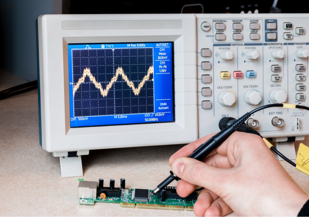
Measure the voltage output from the battery and voltage regulators using a multimeter. Pacemaker PCBs typically operate within a narrow voltage range (e.g., 2.5V to 3.3V). If the measured voltage falls outside this range, replace the battery or inspect the regulator circuit for faults. Check for ripple voltage using an oscilloscope; excessive ripple (above 50mV) can indicate capacitor failure.
Step 3: Check Signal Integrity
Use an oscilloscope to monitor key signals, such as pacing pulses and sensing inputs. Pacemaker circuits often generate pulses with specific widths (e.g., 0.5ms to 1.5ms) and amplitudes (e.g., 2V to 5V). Deviations from expected values may point to issues with the microcontroller or associated components like amplifiers.
Step 4: Test Individual Components
Perform component failure analysis in pacemakers by testing resistors, capacitors, and diodes with a multimeter. For example, a capacitor with a rated value of 10μF should not measure significantly lower (e.g., below 8μF), as this indicates degradation. Replace any out-of-spec components to restore functionality.
Step 5: Inspect for EMI Effects
If the pacemaker malfunctions in specific environments, EMI could be the culprit. Test the device in a controlled setting using a Faraday cage to block external interference. If issues persist, check shielding components or filters on the PCB for damage or improper installation.
Pacemaker PCB Repair Techniques
Once you've identified the issue through troubleshooting, the next step is applying effective pacemaker PCB repair techniques. Here are some practical methods tailored for medical PCBs:
Replacing Faulty Components
If a specific component like a capacitor or resistor has failed, carefully desolder it using a low-temperature soldering iron (around 260°C) to avoid damaging nearby traces. Replace it with a component of identical specifications, ensuring it meets medical-grade standards for reliability and biocompatibility.
Repairing Solder Joints
For cracked or broken solder joints, clean the area with isopropyl alcohol and a brush to remove debris. Apply flux and re-solder the joint using lead-free solder compatible with medical devices. Inspect the joint under magnification to confirm a solid connection without cold solder defects.
Addressing Corrosion
If moisture has caused corrosion, gently clean the affected area with a soft brush and a specialized PCB cleaner. Avoid abrasive methods that could damage traces. After cleaning, apply a conformal coating to protect the area from future moisture exposure, ensuring the coating is approved for medical use.
Enhancing EMI Protection
To mitigate EMI issues, consider adding or replacing ferrite beads or EMI filters near sensitive input lines. Ensure that the PCB design includes proper grounding planes to minimize noise. If redesigning isn't an option, external shielding solutions can be applied during testing phases.
Component Failure Analysis in Pacemakers
Component failure analysis in pacemakers is a critical part of troubleshooting and repair. Understanding why a component failed can prevent future issues and improve design reliability. Here are key aspects to consider during analysis:
- Thermal Stress: Components near high-current paths or voltage regulators may overheat, leading to failure. Measure operating temperatures with a thermal camera; temperatures exceeding 85°C for prolonged periods often indicate a design flaw or inadequate heat dissipation.
- Electrical Overstress: Exceeding a component's voltage or current rating can cause immediate failure. For instance, a transient spike above 5V on a 3.3V-rated microcontroller pin can damage it. Review logs or use a transient voltage suppressor (TVS) diode for protection in future designs.
- Material Aging: Over years of operation, materials in capacitors or batteries degrade. Check manufacturing dates and replace components approaching their rated lifespan (e.g., 5-7 years for certain capacitors).
Documenting failure analysis results helps build a knowledge base for future troubleshooting. Use this data to recommend design improvements, such as selecting components with higher tolerances or adding protective circuits.
Preventing Future Pacemaker PCB Issues
While troubleshooting and repair are essential, preventing issues before they occur is even better. Here are proactive steps to enhance the reliability of pacemaker PCBs:
- Robust Design Practices: Incorporate redundancy in critical circuits, such as dual power supply paths, to ensure functionality even if one path fails.
- Thorough Testing: Subject PCBs to environmental stress tests, including temperature cycling (e.g., -20°C to 60°C) and humidity exposure (up to 95% RH), to identify weak points before deployment.
- Quality Components: Use only medical-grade components with proven reliability under long-term operation. Verify supplier certifications and batch testing data.
- Regular Maintenance: For non-implantable test units, schedule periodic inspections to catch early signs of wear or degradation.
Challenges in Debugging Pacemaker PCB Circuits
Debugging pacemaker PCB circuits comes with unique challenges due to the device's critical nature and compact design. Here are some hurdles and how to overcome them:
- Limited Access: Pacemaker PCBs are often encased in protective housings, making physical access difficult. Use non-invasive diagnostic tools like X-ray imaging to inspect internal components without disassembly.
- High Sensitivity: Small changes in impedance (e.g., from 50Ω to 75Ω) can disrupt pacing signals. Use precision measurement tools to detect subtle variations during debugging.
- Regulatory Constraints: Repairs must comply with strict medical standards. Ensure all materials and methods meet regulatory requirements, such as ISO 13485 for medical device quality management.
Navigating these challenges requires patience, specialized equipment, and adherence to best practices in medical electronics repair.
Conclusion: Ensuring Pacemaker PCB Reliability
Troubleshooting medical PCBs, particularly for pacemakers, is a complex but vital task to ensure patient safety and device performance. By understanding common pacemaker PCB failure modes, applying systematic troubleshooting methods, and using effective repair techniques, you can resolve issues efficiently. Component failure analysis in pacemakers further aids in preventing recurring problems, while proactive design and testing practices enhance long-term reliability.
At ALLPCB, we are committed to supporting engineers and technicians with high-quality PCB solutions tailored for critical applications like medical devices. Whether you're debugging pacemaker PCB circuits or designing new boards, our expertise and resources are here to help you succeed. Use this guide as your roadmap to tackle challenges and maintain the integrity of life-saving technologies.


