ALLPCB


In the world of PCB manufacturing, drill size plays a critical role in both performance and cost. If you're searching for answers on "PCB drill size cost," "smallest drill size for PCB," or "minimum drill size PCB fabrication," you're likely wondering how to strike the right balance between quality and budget. The quick answer: smaller drill sizes often increase manufacturing costs due to precision requirements and tool wear, while larger sizes can reduce expenses but may compromise design performance. The minimum drill size for most standard PCB fabrication processes typically starts at around 0.2 mm (8 mils), though advanced processes can go smaller with added cost.
In this detailed guide, we'll explore how drill sizes impact PCB price, the challenges of using the smallest drill sizes, and strategies for optimizing PCB drill sizes for cost reduction. Whether you're a design engineer or a procurement specialist, this post will help you make informed decisions to achieve high-quality boards without breaking the bank.
Why Drill Size Matters in PCB Manufacturing
Drilling is one of the most time-consuming and expensive steps in PCB production. Each hole on a printed circuit board serves a purpose, whether it's for mounting components, creating vias for electrical connections, or securing the board in an enclosure. The size of these holes—referred to as drill size—directly influences the board's functionality and the overall manufacturing cost.
Smaller drill sizes are often necessary for modern, high-density designs where space is limited. However, they require specialized equipment, slower drilling speeds, and more frequent tool replacements due to wear. On the other hand, larger drill sizes are easier and faster to produce, reducing fabrication time and cost but potentially limiting design flexibility. Understanding this trade-off is key to balancing performance with budget constraints.
What Is the Smallest Drill Size for PCB Fabrication?
The smallest drill size for PCB fabrication depends on the capabilities of the manufacturer and the technology used. For standard PCB production, the minimum drill size typically starts at 0.2 mm (8 mils). This size is commonly used for vias in multilayer boards and is achievable with conventional mechanical drilling methods.
For advanced applications, such as high-density interconnect (HDI) boards used in smartphones and wearables, drill sizes can go as small as 0.1 mm (4 mils) or even less with laser drilling technology. However, these ultra-small holes come with significant challenges, including higher costs, longer production times, and increased risk of drill bit breakage. Additionally, the aspect ratio (the ratio of hole depth to diameter) must be carefully managed to ensure reliable plating and electrical performance.
It's worth noting that not all manufacturers support the smallest drill sizes. Before finalizing your design, confirm the minimum drill size capabilities with your fabrication partner to avoid costly redesigns or delays.
How Drill Size Affects PCB Price
The relationship between drill size and PCB price is straightforward: smaller holes generally cost more to produce. Let's break down the key factors that contribute to this cost increase:
- Precision Equipment: Smaller drill sizes require high-precision machines that can maintain tight tolerances. These machines are expensive to operate and maintain, driving up costs.
- Tool Wear and Replacement: Small drill bits wear out faster and are more prone to breakage, especially when drilling through tough materials like FR-4 or high-Tg laminates. Frequent tool replacements add to the overall expense.
- Slower Production Times: Drilling smaller holes often requires slower speeds to prevent overheating and ensure accuracy. This increases machine time, which translates to higher labor and operational costs.
- Higher Defect Rates: Smaller holes are more susceptible to issues like misalignment or incomplete plating, leading to a higher likelihood of defects and rework, further increasing costs.
For example, a PCB with hundreds of 0.2 mm vias will cost more to produce than one with 0.5 mm vias, even if the board dimensions and layer count are identical. As a general rule, each reduction in drill size below 0.3 mm can increase costs by 10-20%, depending on the complexity of the design and the manufacturer's capabilities.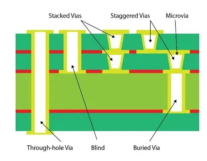
Minimum Drill Size in PCB Fabrication: Challenges and Considerations
While using the minimum drill size in PCB fabrication can enable compact, high-performance designs, it comes with several challenges that designers must consider:
- Aspect Ratio Limitations: The aspect ratio of a drilled hole is critical for reliable plating and signal integrity. For mechanical drilling, a common aspect ratio limit is 10:1 (e.g., a 0.2 mm hole can be drilled up to 2 mm deep). Exceeding this ratio can lead to poor copper plating inside the hole, causing electrical failures.
- Signal Integrity Issues: In high-speed designs, smaller vias can reduce parasitic capacitance and improve signal performance. However, if the holes are not drilled or plated correctly, they can introduce signal loss or crosstalk, negating the intended benefits.
- Manufacturing Constraints: Not all fabrication houses can handle drill sizes below 0.2 mm without specialized equipment or processes like laser drilling. This limits your choice of suppliers and can increase lead times.
To mitigate these challenges, designers should aim to use the largest possible drill size that meets their performance requirements. Additionally, working closely with your manufacturer during the design phase can help identify potential issues before production begins.
Optimizing PCB Drill Sizes for Cost Reduction
Optimizing PCB drill sizes for cost reduction is a practical way to keep your project within budget without sacrificing quality. Here are actionable strategies to achieve this balance:
1. Use Standard Drill Sizes Whenever Possible
Most manufacturers maintain a set of standard drill sizes (e.g., 0.3 mm, 0.5 mm, 1.0 mm) that align with commonly used components and design requirements. Using these sizes reduces setup time and tool changes, lowering costs. Avoid custom or non-standard drill sizes unless absolutely necessary, as they often require special tools and additional setup fees.
2. Minimize the Number of Unique Drill Sizes
Each unique drill size in your design requires a separate tool and setup, increasing production time and cost. For instance, a design with five different drill sizes (0.2 mm, 0.3 mm, 0.5 mm, 0.8 mm, and 1.0 mm) will be more expensive to produce than one with just two sizes (0.3 mm and 1.0 mm). Consolidate drill sizes where possible to streamline the manufacturing process.
3. Balance Small Vias with Design Needs
While smaller vias save space, they aren't always necessary. For low-speed or low-density designs, larger vias (e.g., 0.4 mm or 0.5 mm) can provide adequate performance at a lower cost. Reserve micro vias (below 0.2 mm) for high-speed or HDI applications where signal integrity is critical, such as in boards operating above 1 GHz.
4. Consider Alternative Technologies
For designs requiring ultra-small holes, explore alternatives like laser drilling or blind/buried vias. While these technologies are more expensive upfront, they can reduce the need for multiple drill sizes and layers, potentially offsetting costs in complex designs. Discuss these options with your fabrication partner to determine the most cost-effective approach.
5. Leverage Design Software for Optimization
Modern PCB design tools often include features to check drill size tolerances and optimize hole placement. Use design rule checks (DRCs) to ensure your drill sizes align with manufacturing capabilities and avoid errors that could lead to costly rework. These tools can also help identify opportunities to standardize or reduce the number of unique drill sizes in your layout.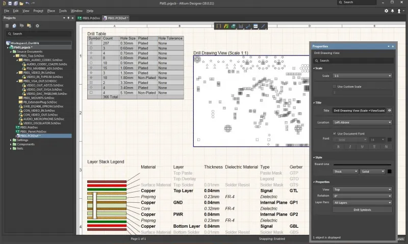
Practical Examples: Drill Size Impact on Real-World Designs
To illustrate how drill size affects both cost and performance, let's look at two hypothetical PCB designs:
- Example 1: Consumer Electronics Board
A 4-layer PCB for a consumer gadget requires 200 vias for signal routing. Using a minimum drill size of 0.2 mm allows for a compact layout but increases fabrication costs by 15% compared to using 0.4 mm vias. Since the board operates at low frequencies (under 100 MHz), signal integrity isn't a concern, and opting for the larger 0.4 mm vias saves money without impacting performance. - Example 2: High-Speed Networking Board
A 6-layer PCB for a networking device operates at 2.5 GHz, requiring tight control over signal integrity. Here, micro vias of 0.15 mm are used to minimize parasitic effects, even though they add 25% to the drilling cost. The performance benefits justify the expense, as larger vias would introduce unacceptable signal loss.
These examples show that the choice of drill size should always align with the specific needs of your application. By carefully evaluating performance requirements, you can avoid unnecessary costs associated with overly small drill sizes.
Collaborating with Your Manufacturer for Cost-Effective Drilling
One of the most effective ways to manage PCB drill size costs is to collaborate closely with your manufacturer. Early communication can help you understand their drilling capabilities, standard tool sizes, and cost structures. Many manufacturers provide design guidelines or feedback during the design review process to help optimize your board for production.
For instance, if your design includes drill sizes below the manufacturer's standard minimum, they might suggest slight adjustments to avoid premium charges. They can also advise on aspect ratios and plating requirements to ensure reliable results without over-specifying hole sizes.
Conclusion: Striking the Right Balance with PCB Drill Sizes
Finding the sweet spot between minimum drill size and PCB manufacturing costs requires a clear understanding of your design goals and budget constraints. While smaller drill sizes like 0.2 mm or below enable cutting-edge, high-density designs, they come with higher costs due to precision requirements and tool wear. On the other hand, sticking to larger, standard drill sizes can significantly reduce expenses, provided they meet your performance needs.
By focusing on strategies like using standard drill sizes, minimizing unique hole sizes, and leveraging design tools, you can optimize PCB drill sizes for cost reduction without compromising quality. Additionally, partnering with your manufacturer early in the design process ensures that your drill specifications align with their capabilities, preventing delays and unexpected expenses.
At the end of the day, the goal is to create a PCB that delivers reliable performance while staying within budget. With careful planning and the right approach to drill size selection, you can achieve both. If you're ready to start your next project, ensure your design prioritizes both functionality and cost-efficiency for the best possible outcome.