 ALLPCB


Are you looking to build a DIY fitness tracker or homebrew fitness monitor without breaking the bank? Designing a low-cost PCB (Printed Circuit Board) for hobby electronics is entirely possible with the right approach. In this guide, we’ll walk you through the essentials of creating an affordable PCB for fitness gadgets, using basic PCB design techniques and budget-friendly materials. Whether you're a beginner or an experienced maker, you’ll find practical tips and step-by-step advice to bring your project to life.
Below, we dive deep into the process of designing a PCB for DIY fitness gadgets, covering everything from choosing low-cost materials to assembling your device. Let’s get started on crafting a functional and affordable fitness tracker PCB!
Why Build a DIY Fitness Tracker PCB?
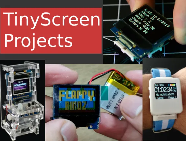
Fitness gadgets like step counters, heart rate monitors, and calorie trackers have become popular tools for health enthusiasts. While commercial products are widely available, building your own fitness monitor offers customization, learning opportunities, and significant cost savings. A DIY fitness tracker PCB lets you tailor the features to your needs—whether it’s a simple step counter or a more complex device with heart rate sensing.
By focusing on low-cost PCB materials and basic design techniques, hobbyists can create effective devices for under $50, depending on the components and tools used. Plus, working on such projects enhances your skills in electronics and circuit design, making it a rewarding endeavor for hobby electronics enthusiasts.
Getting Started with Basic PCB Design for Fitness Gadgets
Before diving into the technical details, it’s important to understand the basics of PCB design. A PCB is the foundation of any electronic device, providing a platform to connect components like sensors, microcontrollers, and batteries. For a DIY fitness tracker, the PCB needs to be compact, efficient, and cost-effective.
Here are the key steps to start designing your PCB for a homebrew fitness monitor:
1. Define Your Fitness Gadget’s Features
Start by deciding what your fitness tracker will do. Common features include:
- Step counting using an accelerometer (e.g., MPU-6050, priced around $3-5).
- Heart rate monitoring with an optical sensor (e.g., MAX30102, costing about $4-6).
- Display for data output, such as a small OLED screen (around $2-4).
- Bluetooth connectivity for data transfer to a smartphone (using modules like HC-05, under $5).
Keep your feature list simple to manage costs. For a beginner, focusing on one or two functions like step counting and basic data display is a great starting point.
2. Choose a Microcontroller
The microcontroller (MCU) is the brain of your fitness tracker. For low-cost projects, consider using an Arduino-compatible board like the Nano, which costs around $3-5. It’s beginner-friendly and supports a wide range of sensors. For more compact designs, a bare MCU chip like the ATmega328P (under $2) can be used, though it requires additional programming knowledge.
3. Plan Your Power Source
Fitness trackers need to be portable, so a small rechargeable battery, such as a 3.7V LiPo battery (around $2-3 for 100mAh), works well. Include a charging circuit using a TP4056 module (under $1) to manage battery power safely. Ensure your PCB design accounts for low power consumption by selecting components with minimal current draw (e.g., sleep modes on MCUs can reduce power to under 1mA).
Selecting Low-Cost PCB Materials
One of the biggest challenges in hobby electronics is keeping costs down without sacrificing quality. When designing a PCB for a DIY fitness tracker, material selection plays a critical role in both performance and price.
1. PCB Substrate Material
The most common and affordable PCB material is FR-4, a fiberglass-epoxy laminate. It’s widely available, durable, and suitable for most fitness gadgets. A standard 1.6mm thick, double-sided FR-4 board can cost as little as $1-2 per square inch for small quantities. For wearables, where size matters, aim for a compact board (e.g., 30mm x 30mm) to minimize material costs.
2. Copper Thickness
Copper thickness affects the PCB’s ability to handle current. For low-power fitness trackers, a 1oz copper layer (standard thickness) is sufficient and keeps costs low. Thicker copper (e.g., 2oz) increases expenses and is unnecessary unless your design involves high-current components.
3. Surface Finish
The surface finish protects the copper traces from oxidation. HASL (Hot Air Solder Leveling) is the cheapest option, often included in standard PCB fabrication packages. It’s reliable for hobby projects and works well for hand-soldering components. Avoid pricier finishes like ENIG (Electroless Nickel Immersion Gold) unless your design requires finer trace widths below 0.2mm.
4. Sourcing Components
Purchase components from affordable online marketplaces. Look for bulk deals on resistors, capacitors, and LEDs, which can cost pennies per piece when bought in lots of 100. Sensors and modules for fitness trackers are often available at low prices on platforms catering to hobbyists. Always check for datasheets to ensure compatibility with your design.
Designing Your PCB Layout for a Homebrew Fitness Monitor
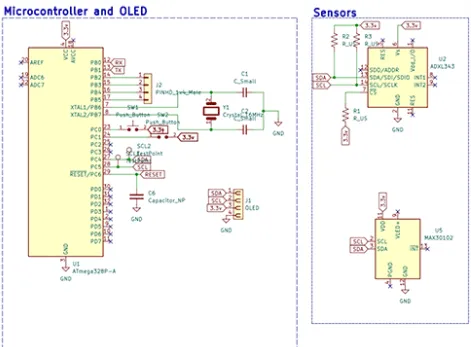
With materials and components selected, the next step is designing the PCB layout. This process involves creating a schematic (a blueprint of connections) and then arranging components on the board. Here’s how to approach it using basic PCB design techniques:
1. Use Free Design Software
Several free tools are available for hobbyists to design PCBs. These programs offer user-friendly interfaces and libraries of components to simplify the process. Start with a schematic editor to connect your microcontroller, sensors, and power supply, then move to the layout editor to place components and route traces.
2. Keep the Layout Compact
Fitness trackers are wearables, so space is limited. Aim for a board size under 40mm x 40mm to fit into a small enclosure or wristband. Place components close together, but maintain at least 0.3mm spacing between traces to avoid short circuits. Group related components (e.g., power circuitry near the battery) to minimize trace lengths and reduce signal interference.
3. Optimize for Low Noise
Sensors like heart rate monitors are sensitive to electrical noise. Use a ground plane (a large copper area connected to ground) on one layer of your PCB to shield against interference. Keep analog signals (from sensors) away from digital signals (from the MCU) by routing them on separate paths. For a heart rate sensor like the MAX30102, ensure stable power delivery by adding a 0.1μF decoupling capacitor near its power pin.
4. Test Your Design
Before sending your design for fabrication, use the design rule check (DRC) feature in your software to catch errors like unconnected pins or overlapping traces. Simulate the circuit if possible to verify signal integrity. For instance, ensure the I2C lines for your accelerometer have pull-up resistors (typically 4.7kΩ) to maintain signal levels around 3.3V or 5V, depending on your MCU.
Fabricating Your Low-Cost PCB
Once your design is ready, it’s time to manufacture the PCB. For hobbyists, there are two main options to keep costs low:
1. Home Etching
If you’re on a tight budget, you can etch your PCB at home using a copper-clad board, ferric chloride, and a laser-printed mask. This method costs under $10 for materials but requires time and safety precautions due to the chemicals involved. It’s best for single-layer boards with simple designs. Expect trace widths no finer than 0.5mm with this method.
2. Professional Fabrication Services
For better quality and multi-layer boards, use an affordable online fabrication service. Many providers offer small-batch PCBs (e.g., 5 pieces) for as low as $5-10, including shipping, for boards under 100mm x 100mm. Upload your design files in Gerber format, select standard options like 1.6mm FR-4 and HASL finish, and you’ll receive professional-grade boards in about a week.
Assembling Your DIY Fitness Tracker
After receiving your PCB, it’s time to assemble the components. Here’s how to do it on a budget:
1. Soldering Tools
A basic soldering iron (around $10) and lead-free solder (under $5 for a spool) are sufficient for hobby electronics. Use a magnifying glass or a cheap USB microscope (around $15) to inspect small connections on compact boards.
2. Component Placement
Start by soldering low-profile components like resistors and capacitors, then move to larger ones like sensors and the MCU. Follow the silkscreen markings on your PCB (if included) to ensure correct placement. For surface-mount components, use a small amount of solder paste and a hot air rework station if available, though hand soldering with a fine tip works too.
3. Testing and Debugging
Power up your board with a multimeter to check voltages at key points (e.g., 3.3V or 5V at the MCU pins). Upload a simple test code to your microcontroller to verify sensor readings. For example, an accelerometer should output changing values on the X, Y, and Z axes when moved. If something doesn’t work, inspect solder joints for cold connections and recheck your schematic for errors.
Programming Your Fitness Tracker
The final step is programming the microcontroller to process sensor data and display or transmit results. Use a free development environment compatible with your MCU. Write code to read data from sensors (e.g., step counts from an accelerometer using a threshold algorithm) and output it to a display or via Bluetooth. Libraries are often available for common sensors, simplifying the coding process.
For power efficiency, program your device to enter sleep mode when idle, reducing current draw to below 100μA. A typical fitness tracker might update step counts every second, so balance refresh rates with battery life.
Tips for Keeping Costs Low in Hobby Electronics
Building a DIY fitness tracker PCB doesn’t have to be expensive. Here are additional tips to save money:
- Reuse components from old electronics, like resistors or LEDs, if they’re in good condition.
- Buy components in bulk to reduce per-unit costs for future projects.
- Stick to standard PCB sizes and specifications to avoid extra fabrication fees.
- Join online communities for hobby electronics to share resources and get free advice on designs.
Conclusion
Designing a low-cost PCB for DIY fitness gadgets is an achievable goal for hobbyists of all skill levels. By focusing on affordable materials like FR-4 boards, using free design tools, and selecting budget-friendly components, you can create a functional homebrew fitness monitor without spending a fortune. Follow basic PCB design techniques to ensure a compact, noise-free layout, and test your device thoroughly before finalizing the build.
With the steps outlined in this guide, you’re well on your way to crafting a custom fitness tracker PCB that meets your needs. Start small, experiment with features, and enjoy the process of bringing your hobby electronics project to life. Your journey into DIY fitness gadgets begins with a single board—make it count!


