 ALLPCB


When designing a printed circuit board (PCB), one of the most critical decisions is selecting the right material. The material not only affects performance factors like signal integrity and thermal management but also plays a significant role in PCB thickness tolerance. So, how does material selection impact thickness tolerance, and what should you consider when choosing between FR-4 and alternatives like high-Tg materials or Rogers laminates? In short, FR-4 offers a cost-effective solution with moderate thickness tolerance, typically ±10%, while alternatives like Rogers materials provide tighter tolerances (often or better for the base laminate thickness) for high-frequency or high-reliability applications, though at a higher cost. In this blog, we’ll dive deep into the nuances of PCB material thickness tolerance comparison, exploring FR-4 thickness tolerance, Rogers PCB thickness tolerance, and high-Tg PCB thickness tolerance to help you make informed decisions for your projects.
Why PCB Thickness Tolerance Matters in Design
PCB thickness tolerance refers to the allowable variation in the final thickness of a board during manufacturing. This parameter is crucial because even small deviations can impact the board’s mechanical fit, electrical performance, and overall reliability. For instance, if a PCB is too thick or thin, it may not fit into a device’s enclosure or connectors, leading to assembly issues. Additionally, thickness variations can affect impedance control in high-frequency designs, where consistent dielectric thickness is vital for signal integrity.
Material selection directly influences how tightly manufacturers can control thickness. Different materials have unique properties, such as thermal expansion rates and manufacturing behaviors, that affect the final outcome. Understanding these differences is key to achieving the desired performance and reliability in your PCB designs.
FR-4: The Standard Choice and Its Thickness Tolerance
FR-4 is the most widely used PCB material, known for its affordability, versatility, and decent mechanical strength. Made from woven fiberglass cloth with an epoxy resin binder, FR-4 is suitable for a wide range of applications, from consumer electronics to industrial equipment. However, when it comes to FR-4 thickness tolerance, there are limitations to consider.
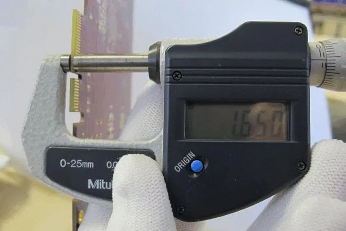
Standard FR-4 boards typically have a thickness tolerance of ±10% as per industry guidelines like those from the Institute of Printed Circuits (IPC). For example, a 1.6mm thick FR-4 board could vary between 1.44mm and 1.76mm. This range is acceptable for many general-purpose applications but may pose challenges in designs requiring precise mechanical fit or controlled impedance. The relatively wide tolerance is due to factors like variations in resin content, curing processes, and fiberglass weave consistency during manufacturing.
Additionally, FR-4’s thermal expansion coefficient (CTE) can contribute to thickness variations under temperature changes. With a CTE of around 14-17 ppm/°C in the Z-axis (thickness direction), FR-4 may expand or contract during soldering or operation, slightly altering its dimensions. For most standard designs, this isn’t a significant issue, but it can be a concern in high-reliability or multilayer boards.
Pros and Cons of FR-4 Thickness Tolerance
- Pros: Cost-effective and widely available, with acceptable tolerance for many applications.
- Cons: Wider tolerance range (±10%) compared to advanced materials, potential for thermal expansion issues.
High-Tg FR-4: Improved Stability for Demanding Applications
For applications requiring better thermal stability and tighter control over dimensions, high-Tg (glass transition temperature) FR-4 is a popular upgrade. Standard FR-4 has a Tg of around 130-140°C, meaning it starts to soften and lose structural integrity above this temperature. High-Tg FR-4, with a Tg of 170-180°C or higher, offers improved resistance to heat, making it ideal for lead-free soldering processes or high-temperature environments.
In terms of high-Tg PCB thickness tolerance, the improvement over standard FR-4 is modest but notable. High-Tg materials often achieve tolerances closer to ±8-10%, thanks to better resin formulations and reduced thermal expansion (CTE around 12-15 ppm/°C in the Z-axis). This makes high-Tg FR-4 a good choice for multilayer boards or designs where thermal stress during assembly could otherwise cause dimensional shifts.
For instance, in a 6-layer PCB design for automotive electronics, using high-Tg FR-4 can minimize thickness variations during reflow soldering, ensuring consistent layer spacing and impedance values. However, the cost of high-Tg FR-4 is slightly higher than standard FR-4, though still more affordable than advanced alternatives.
Pros and Cons of High-Tg FR-4 Thickness Tolerance
- Pros: Better thermal stability and slightly tighter tolerance than standard FR-4.
- Cons: Still not as precise as specialty materials for high-frequency or ultra-reliable designs.
Rogers Materials: Precision for High-Frequency Needs
When precision and performance outweigh cost considerations, Rogers laminates are often the material of choice, especially for high-frequency and RF (radio frequency) applications. Unlike FR-4, which has a relatively high dielectric constant (Dk of 4.4-4.8) leading to signal loss at frequencies above 1 GHz, Rogers materials offer low Dk values (around 2.5-3.0) and low dissipation factors (Df), ensuring minimal signal attenuation.
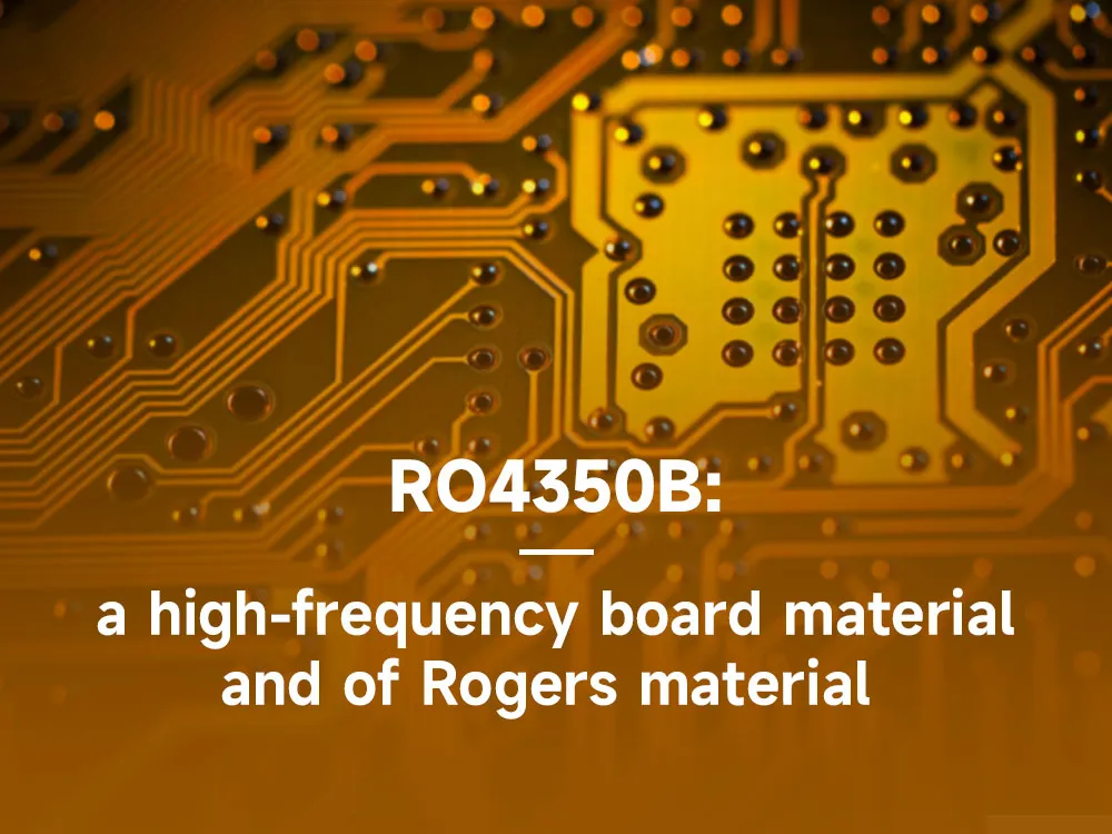
Regarding Rogers PCB thickness tolerance, these materials stand out for their precision. Rogers laminates typically achieve tolerances of ±5% or better, thanks to their consistent dielectric properties and advanced manufacturing processes. It is important to note that Rogers tolerances are typically specified for the base laminate (core) thickness, not the final finished PCB thickness. For example, a Rogers RO4350B laminate core with a nominal thickness of 0.508mm (20 mils) might vary only between 0.483mm and 0.533mm. This tight control is critical in RF designs where dielectric thickness directly affects impedance—often requiring values like 50 ohms for optimal signal transmission.
Moreover, Rogers materials have a lower CTE (around 10-12 ppm/°C in the Z-axis) compared to FR-4, reducing the risk of thickness changes under thermal stress. This makes them ideal for applications like aerospace, telecommunications, and medical devices where reliability is non-negotiable. However, the trade-off is cost—Rogers materials can be several times more expensive than FR-4.
Pros and Cons of Rogers PCB Thickness Tolerance
- Pros: Extremely tight laminate core tolerance (±5% or better), excellent for high-frequency and high-reliability designs.
- Cons: Significantly higher cost compared to FR-4 and high-Tg options.
Comparing PCB Material Thickness Tolerance: FR-4 vs. High-Tg vs. Rogers
To make the best material choice for your PCB design, it’s helpful to directly compare the thickness tolerances and related properties of FR-4, high-Tg FR-4, and Rogers materials. Below is a summary table for quick reference:
| Material | Typical Thickness Tolerance | CTE (Z-axis, ppm/°C) | Cost | Best For |
|---|---|---|---|---|
| Standard FR-4 | ±10% | 14-17 | Low | General-purpose, cost-sensitive designs |
| High-Tg FR-4 | ±8-10% | 12-15 | Moderate | High-temperature, multilayer designs |
| Rogers Laminates | ±5% or better | 10-12 | High | High-frequency, RF, and precision applications |
This PCB material thickness tolerance comparison shows that while FR-4 is suitable for many applications, it falls short in precision compared to high-Tg variants and Rogers materials. If your design involves high-speed signals (e.g., above 5 GHz) or strict impedance control (e.g., maintaining 50 ohms with minimal deviation), opting for Rogers could save you from costly redesigns. On the other hand, for simpler circuits or prototypes, standard FR-4’s tolerance is often sufficient.
Factors Beyond Material That Affect Thickness Tolerance
While material selection is a primary driver of PCB thickness tolerance, other factors during design and manufacturing also play a role. Understanding these can help you achieve better control over the final product:
- Layer Count: Multilayer boards, especially those with 8 or more layers, are more prone to thickness variations due to the stacking of prepreg and core materials. High-Tg or Rogers materials can mitigate this by providing more consistent layer bonding.
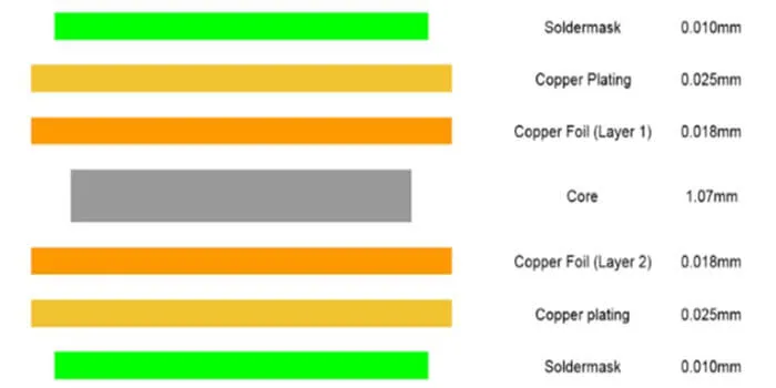
- Copper Thickness: The weight of copper used (e.g., 1 oz/ft2 or 2 oz/ft2) adds to the overall thickness. Variations in copper etching can introduce small deviations, regardless of the base material.
- Manufacturing Process: The lamination and curing processes can introduce inconsistencies, especially with FR-4 if temperature and pressure aren’t tightly controlled. Advanced materials like Rogers often come with stricter manufacturing guidelines to ensure precision.
Working closely with your PCB fabrication partner to specify tolerances and material requirements can help minimize these variables. For critical designs, consider requesting test coupons or samples to verify thickness before full production.
How to Choose the Right Material for Your PCB Thickness Needs
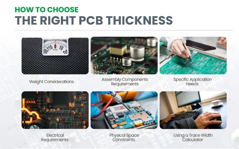
Selecting the right PCB material for thickness tolerance involves balancing performance requirements with budget constraints. Here are some practical steps to guide your decision:
- Define Your Application: Determine if your design needs high-frequency performance, thermal stability, or just basic functionality. For example, a smartphone PCB might use FR-4, while a satellite communication board may require Rogers laminates.
- Assess Tolerance Requirements: Check if your mechanical or electrical design can accommodate a ±10% variation (FR-4) or if it demands tighter control (±5% with Rogers laminates).
- Consider Environmental Factors: If your PCB will face high temperatures or thermal cycling, opt for high-Tg FR-4 or Rogers to reduce the risk of dimensional changes.
- Evaluate Cost: Weigh the benefits of tighter tolerance against the price. If budget is a concern, high-Tg FR-4 often provides a middle ground between standard FR-4 and premium materials.
By aligning material properties with your project’s specific needs, you can avoid over-specifying (and overspending) or under-specifying (and risking failure).
Conclusion: Making an Informed Choice for PCB Thickness Tolerance
Material selection is a cornerstone of PCB design, and its impact on thickness tolerance cannot be overstated. FR-4 remains a reliable and affordable option for many projects, with a thickness tolerance of ±10% that suits general-purpose applications. For designs requiring better thermal stability, high-Tg FR-4 offers a slight improvement at ±8-10%, while Rogers materials provide unparalleled precision with laminate core tolerances of ±5% or better, ideal for high-frequency and high-reliability needs.
Understanding the nuances of PCB material thickness tolerance comparison—whether it’s FR-4 thickness tolerance, Rogers PCB thickness tolerance, or high-Tg PCB thickness tolerance—empowers you to make choices that optimize both performance and cost. By considering factors like application requirements, environmental conditions, and manufacturing variables, you can ensure your PCB meets the necessary standards for fit, function, and durability.


