 ALLPCB


In the world of electronics, flex-to-rigid PCBs (also known as rigid-flex PCBs) are a game-changer, combining the stability of rigid boards with the adaptability of flexible circuits. But how do these hybrid boards hold up in harsh environments like extreme temperatures, high humidity, or constant vibration? The answer lies in careful material selection and understanding reliability factors. In this blog, we dive deep into rigid-flex PCB reliability, material choices for flex PCBs in harsh environments, and key considerations to prevent failures through effective design and analysis.
What Are Flex-to-Rigid PCBs and Why Do They Matter?
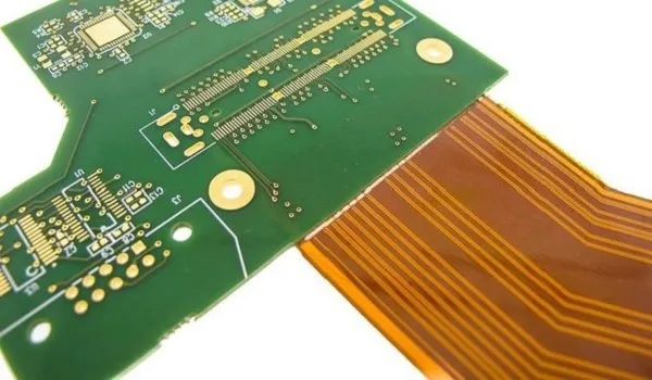
Flex-to-rigid PCBs are hybrid circuit boards that integrate rigid and flexible sections into a single unit. The rigid parts provide structural support and house components, while the flexible sections allow bending and folding, making them ideal for compact designs in industries like aerospace, automotive, medical, and industrial equipment. Their ability to reduce space, weight, and connection points enhances efficiency and durability compared to traditional wiring or separate rigid boards.
In harsh environments—think desert heat, arctic cold, or high-vibration settings like automotive engines—these boards face unique challenges. Temperature swings can cause material expansion or contraction, humidity can lead to corrosion, and mechanical stress can crack traces or delaminate layers. That’s why selecting the right materials and designing for reliability are critical to ensuring performance and longevity.
Challenges of Using Flex-to-Rigid PCBs in Harsh Environments
Harsh environments push electronic components to their limits, and rigid-flex PCBs are no exception. Here are the primary challenges these boards face:
- Thermal Stress: Temperature extremes, such as -40°C to 125°C in automotive applications, cause materials to expand and contract at different rates. This mismatch, known as the coefficient of thermal expansion (CTE), can lead to cracks or delamination between layers.
- Moisture and Humidity: High humidity levels, often exceeding 85% in tropical or marine settings, can penetrate materials, leading to corrosion of copper traces or short circuits.
- Mechanical Stress: Constant vibration or flexing, like in aerospace or wearable devices, can fatigue materials, causing cracks in the flexible sections or solder joint failures.
- Chemical Exposure: Industrial environments may expose boards to chemicals or solvents that degrade materials or coatings, affecting long-term reliability.
Understanding these challenges is the first step to designing boards that can withstand tough conditions. Let’s explore how material selection plays a pivotal role in addressing these issues.
Material Selection for Rigid-Flex PCBs in Harsh Environments
Choosing the right materials for a rigid-flex PCB is crucial for ensuring reliability in extreme conditions. The materials must balance flexibility, thermal stability, and resistance to environmental factors. Here’s a breakdown of key material considerations:
1. Substrate Materials for Flexible Sections
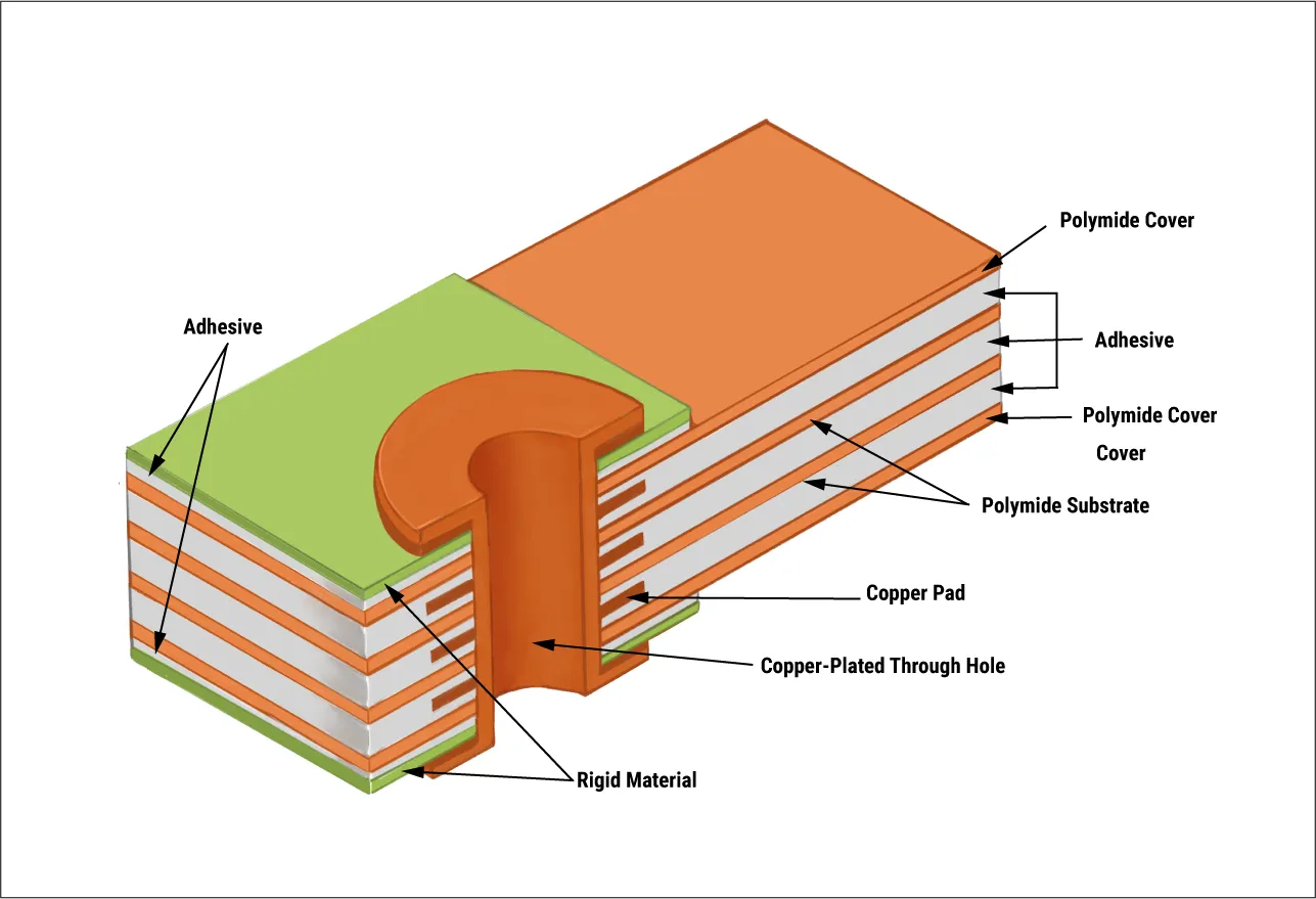
The flexible part of a rigid-flex PCB is typically made from polyimide (PI), a high-performance polymer known for its thermal stability and flexibility. Polyimide can withstand temperatures from -55°C to over 200°C, making it suitable for harsh environments. It also offers excellent resistance to chemicals and moisture.
- Thickness: Polyimide films are available in thicknesses ranging from 12.5 to 125 micrometers. Thinner films (e.g., 25 μm) are more flexible but less durable under mechanical stress, while thicker films provide better tear resistance.
- Dielectric Constant: Polyimide has a dielectric constant of around 3.5, which supports good signal integrity for high-frequency applications often found in aerospace or telecommunications.
2. Rigid Section Materials
The rigid sections often use FR-4, a glass-reinforced epoxy laminate, due to its cost-effectiveness and mechanical strength. However, for harsh environments, high-Tg (glass transition temperature) FR-4 or advanced materials like polyimide-based laminates may be necessary.
- High-Tg FR-4: With a Tg of 170°C or higher, this variant resists deformation at elevated temperatures better than standard FR-4 (Tg around 130°C).
- CTE Matching: Matching the CTE of rigid and flexible materials (e.g., 17-20 ppm/°C for FR-4 and 20-25 ppm/°C for polyimide) reduces stress at transition zones during thermal cycling.
3. Adhesives and Bonding Materials
Adhesives bond the rigid and flexible layers together, and their performance directly impacts reliability. Acrylic or epoxy-based adhesives are common, but for harsh environments, low-flow or no-flow prepregs (pre-impregnated materials) are preferred to prevent squeeze-out during lamination, which can weaken bonds.
- Thermal Resistance: Adhesives must withstand temperatures up to 150°C without degrading.
- Moisture Resistance: Poor adhesive choices can absorb moisture, leading to delamination under high humidity.
4. Copper Foil and Conductive Layers
Copper is the backbone of electrical conductivity in PCBs, but not all copper is equal. Rolled annealed (RA) copper is often used in flexible sections due to its ductility, allowing it to bend without cracking.
- Thickness: Common thicknesses range from 18 μm (0.5 oz) to 35 μm (1 oz). Thinner copper reduces weight but may be prone to tearing under mechanical stress.
- Plating: Electroless nickel immersion gold (ENIG) or hard gold plating protects copper from corrosion in humid or chemical-heavy environments.
5. Protective Coatings and Coverlays
Coverlays (flexible solder masks) or conformal coatings shield the board from environmental damage. Polyimide coverlays provide flexibility and thermal resistance, while liquid photoimageable (LPI) solder masks offer precision for complex designs.
- Conformal Coatings: Parylene or silicone coatings add an extra layer of protection against moisture and chemicals, critical for marine or industrial applications.
- Thickness: Coverlay thickness typically ranges from 25 to 50 μm, balancing protection with flexibility.
Rigid-Flex PCB Reliability: Key Design Considerations
Beyond material selection, the design of a rigid-flex PCB significantly impacts its reliability in harsh environments. Here are some essential factors to keep in mind:
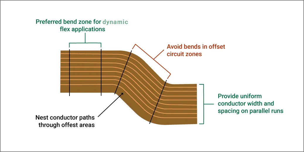
1. Bend Radius and Flex Zone Design
The flexible sections of a rigid-flex PCB must endure repeated bending without failure. A minimum bend radius, often 10 times the thickness of the flex layer, prevents cracking. For example, a 100 μm thick flex layer should have a bend radius of at least 1 mm.
- Transition Zones: The area where rigid meets flexible is prone to stress. Gradual transitions and avoiding vias or components near these zones reduce failure risks.
- Dynamic vs. Static Flex: For dynamic applications (constant bending), use thinner materials and limit the number of copper layers to 1 or 2 to minimize stress.
2. Thermal Management
Heat dissipation is vital in high-temperature environments. Adding thermal vias or using materials with higher thermal conductivity (e.g., polyimide with a thermal conductivity of 0.2 W/m·K compared to FR-4 at 0.3 W/m·K) helps manage heat buildup.
- Component Placement: Place heat-generating components on rigid sections with better heat sinking capabilities.
- Testing: Thermal cycling tests between -40°C and 125°C can simulate real-world conditions to validate design reliability.
3. Signal Integrity
In high-frequency applications, signal integrity can degrade due to impedance mismatches or crosstalk, especially in flexible sections. Controlled impedance design, targeting values like 50 ohms for single-ended traces or 100 ohms for differential pairs, ensures consistent performance.
- Trace Width and Spacing: Maintain consistent trace widths (e.g., 0.1 mm for high-density designs) and spacing to avoid signal loss.
- Ground Planes: Use solid ground planes in rigid sections to reduce electromagnetic interference (EMI).
Rigid-Flex PCB Failure Analysis: Identifying and Preventing Issues
Even with the best materials and design, failures can occur in harsh environments. Conducting a thorough failure analysis helps identify root causes and improve future designs. Here are common failure modes and how to address them:
1. Delamination
Delamination happens when layers separate due to thermal stress or poor adhesive bonding. It’s common in humid environments where moisture weakens bonds.
- Prevention: Use moisture-resistant adhesives and store boards in controlled environments before assembly. Bake-out processes at 120°C for 2-4 hours can remove trapped moisture.
- Analysis: Cross-sectional microscopy can reveal delamination points, helping pinpoint material or process flaws.
2. Copper Trace Cracking
Cracking in copper traces often results from excessive bending or vibration, especially in flex zones.
- Prevention: Use rolled annealed copper for better ductility and design with larger bend radii. Reinforce high-stress areas with stiffeners.
- Analysis: Scanning electron microscopy (SEM) can detect micro-cracks invisible to the naked eye, guiding redesign efforts.
3. Solder Joint Failure
Thermal cycling and vibration can cause solder joints to crack, leading to open circuits.
- Prevention: Use lead-free solders with higher fatigue resistance and avoid placing heavy components in flex zones.
- Analysis: X-ray inspection can identify voids or cracks in solder joints, while thermal imaging detects hotspots indicating poor connections.
Testing for Reliability in Harsh Environments
Testing is a non-negotiable step to ensure rigid-flex PCBs can survive harsh conditions. Industry-standard tests simulate real-world stresses and validate design choices.
- Thermal Cycling: Expose boards to temperature swings (e.g., -40°C to 125°C) for 500-1000 cycles to assess CTE mismatch and material stability.
- Humidity Testing: Test at 85°C and 85% relative humidity for 96 hours to check for moisture ingress and corrosion.
- Vibration Testing: Subject boards to random vibration profiles (e.g., 5-500 Hz at 5G acceleration) to evaluate mechanical durability.
- Flex Cycling: Perform repeated bending (e.g., 10,000 cycles at a specified radius) to ensure flex zones withstand dynamic use.
These tests provide data on potential weaknesses, allowing designers to refine materials or layouts before production.
Conclusion: Building Reliable Rigid-Flex PCBs for Any Environment
Flex-to-rigid PCBs are a powerful solution for compact, durable electronics, but their performance in harsh environments hinges on smart material selection and thoughtful design. By choosing substrates like polyimide for flexibility, high-Tg laminates for thermal stability, and protective coatings for environmental resistance, you can significantly boost rigid-flex PCB reliability. Coupled with proper design practices—such as optimizing bend radii and managing thermal stress—and rigorous testing, these boards can thrive even in the toughest conditions.
Whether you’re designing for aerospace, automotive, or industrial applications, understanding the nuances of material selection for rigid-flex and conducting thorough failure analysis are key to success. With the right approach, your rigid-flex PCBs can deliver exceptional performance no matter the challenge.


