 ALLPCB


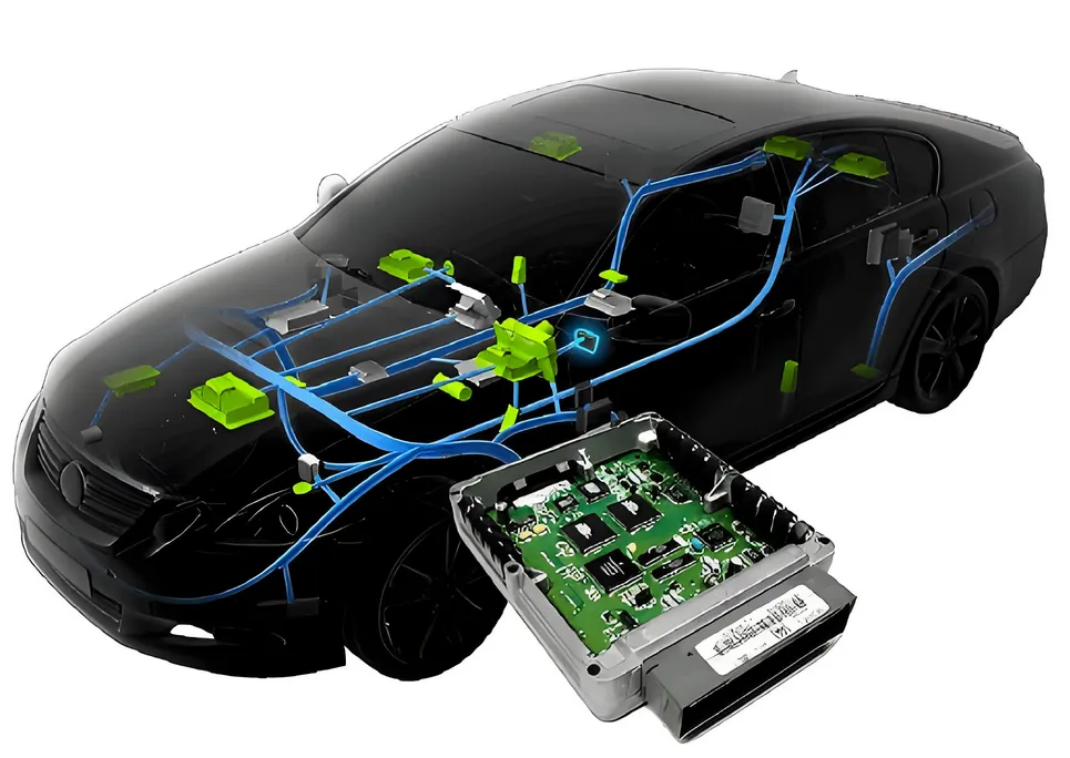
In the fast-evolving world of automotive technology, Electronic Control Units (ECUs) are the heart of modern vehicles, managing everything from engine performance to safety systems. However, the reliability of an ECU depends heavily on the quality of its Printed Circuit Board (PCB). So, how do we ensure that these critical components meet the strict automotive standards? ECU PCB testing and validation are the answer. This process involves a range of methods like functional testing, in-circuit testing, and environmental stress tests to guarantee automotive PCB reliability.
In this comprehensive guide, we’ll dive deep into ECU PCB testing methods, explore automotive PCB validation techniques, and explain how these processes ensure that ECUs perform flawlessly under the toughest conditions. Whether you're an engineer, a manufacturer, or simply curious about automotive electronics, this blog will provide actionable insights into achieving top-tier reliability.
Why ECU PCB Testing and Validation Matter in Automotive Applications
Modern vehicles rely on dozens of ECUs to control critical systems like braking, steering, and fuel injection. A single failure in an ECU PCB can lead to catastrophic consequences, including accidents or costly recalls. Automotive standards, such as ISO 26262 for functional safety, demand rigorous testing to ensure that every component can withstand harsh environments—think extreme temperatures ranging from -40°C to 85°C, vibrations up to 10G, and humidity levels as high as 95%.
ECU PCB testing and validation are not just about meeting regulatory requirements; they’re about building trust in the safety and performance of vehicles. By using advanced testing methods, manufacturers can detect defects early, reduce failure rates, and ensure long-term durability. Let’s explore the key approaches to achieving this.
Key ECU PCB Testing Methods for Automotive Reliability
To ensure that an ECU PCB meets automotive standards, several testing methods are employed throughout the design, manufacturing, and assembly stages. Below, we break down the most critical ECU PCB testing methods that contribute to automotive PCB reliability.
1. In-Circuit Testing (ICT) for ECU PCBs
In-circuit testing (ICT) is a fundamental method used to verify the functionality of individual components on a PCB before full assembly. During ICT, a specialized test fixture with probes contacts specific test points on the board to measure parameters like resistance, capacitance, and voltage. For instance, ICT can detect a faulty resistor with a resistance value deviating beyond the acceptable range of ±5% or identify a short circuit that could cause an ECU to malfunction.
In the context of in-circuit testing ECU boards, this method ensures that every soldered connection and component operates as intended. It’s especially crucial for high-density ECU PCBs, where even a minor defect can disrupt critical signals, such as those controlling engine timing with latencies as low as 1 millisecond.
2. Functional Testing for ECUs
Functional testing ECU boards goes beyond individual components to evaluate the overall performance of the assembled PCB. This method simulates real-world operating conditions to verify that the ECU performs its intended functions, such as processing sensor data or sending control signals. For example, functional testing might involve inputting a simulated wheel speed signal of 50 Hz to ensure the ECU correctly triggers the anti-lock braking system (ABS).
This type of testing is vital for confirming that the ECU integrates seamlessly with other vehicle systems. It often involves automated test equipment (ATE) to run thousands of test cycles, ensuring repeatability and catching intermittent faults that could compromise safety.
3. Environmental Stress Testing for Durability
Automotive PCBs must endure extreme conditions, and environmental stress testing is designed to push them to their limits. This includes thermal cycling between -40°C and 125°C to simulate temperature fluctuations, vibration testing at frequencies up to 200 Hz to mimic road conditions, and humidity exposure to test for corrosion resistance.
These tests are critical for automotive PCB reliability, as they replicate the harsh environments an ECU might face over a vehicle’s 10- to 15-year lifespan. A well-designed PCB should maintain signal integrity with impedance values within ±10% of the target, even after thousands of thermal cycles.
4. Automated Optical Inspection (AOI) for Manufacturing Quality
Before functional or environmental tests, Automated Optical Inspection (AOI) is used during manufacturing to detect physical defects on the PCB. High-resolution cameras scan the board for issues like misaligned components, soldering defects, or missing parts. For ECU PCBs, where a single misplaced capacitor can disrupt a 5V power supply line, AOI ensures precision at the earliest stage.
This non-invasive method is fast and effective, often inspecting hundreds of boards per hour, making it a cornerstone of quality control in high-volume automotive production.
Automotive PCB Validation: Meeting Industry Standards
Testing is only part of the equation; automotive PCB validation ensures that the design and manufacturing processes align with industry standards. Validation focuses on long-term reliability and safety, addressing potential risks before they become real-world problems. Here’s how validation complements testing in the ECU development cycle.
1. Design Validation with Simulation Tools
Before a single PCB is manufactured, design validation uses simulation software to model the ECU’s performance under various conditions. For instance, signal integrity simulations can predict whether a high-speed CAN bus signal operating at 1 Mbps will maintain clarity across the PCB traces, avoiding data loss or electromagnetic interference (EMI).
This step is crucial for identifying design flaws early, reducing the need for costly revisions. It also ensures compliance with standards like ISO 26262, which mandates risk assessment for functional safety.
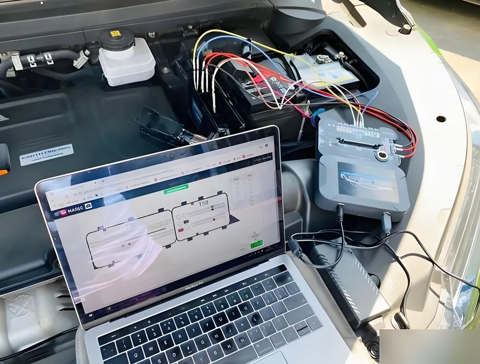
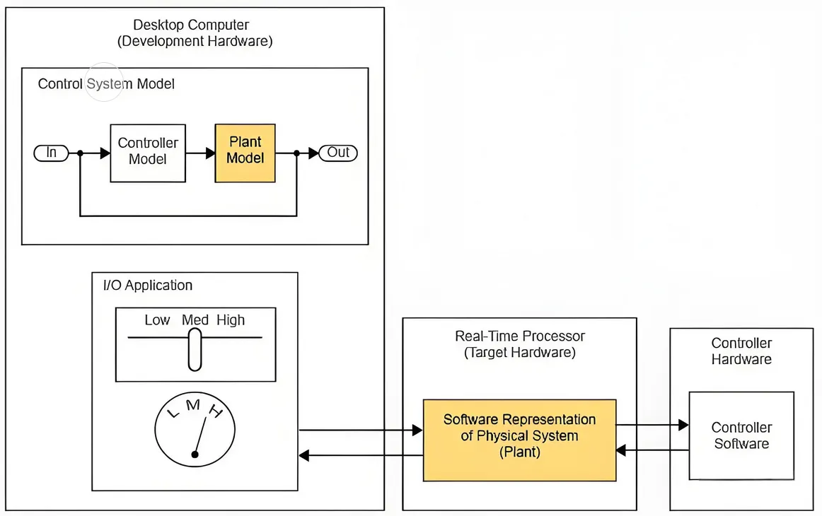
2. Hardware-in-the-Loop (HIL) Testing for System Integration
Hardware-in-the-Loop (HIL) testing is a powerful validation technique that integrates the ECU with a simulated vehicle environment. HIL systems replicate real-time inputs, such as engine RPM signals ranging from 0 to 6000, allowing engineers to observe how the ECU responds without needing a physical vehicle.
HIL testing is essential for validating complex systems like Advanced Driver Assistance Systems (ADAS), where the ECU must process multiple sensor inputs with response times under 10 milliseconds. It bridges the gap between isolated testing and real-world application.
3. Compliance with Automotive Standards
Automotive PCB validation isn’t complete without adherence to global standards. ISO 26262, for example, defines Automotive Safety Integrity Levels (ASIL) to classify the risk of system failures. An ECU controlling a critical function like braking might require ASIL-D, the highest level, demanding failure rates below 10^-8 per hour.
Other standards, such as AEC-Q100 for electronic component reliability, specify test conditions like 1000 hours of high-temperature operation at 125°C. Validation ensures that every aspect of the ECU PCB—from material selection to final assembly—meets these stringent criteria.
Challenges in ECU PCB Testing and Validation
Despite the advancements in testing technology, ECU PCB testing and validation come with significant challenges. The increasing complexity of automotive electronics, with some high-end vehicles containing over 100 ECUs, means more potential failure points. Miniaturization also complicates testing, as densely packed components make it harder to access test points for in-circuit testing ECU boards.
Additionally, the rise of electric and autonomous vehicles introduces new requirements, such as higher power densities and faster data processing. These trends demand innovative testing solutions, like machine learning algorithms for predictive failure analysis, to keep pace with evolving technology.
Best Practices for Ensuring Automotive PCB Reliability
To maximize the effectiveness of ECU PCB testing and validation, manufacturers should adopt the following best practices:
- Early Integration of Testing: Incorporate testing into the design phase to catch issues before production. For example, use Design for Testability (DFT) principles to ensure adequate test point access for ICT.
- Comprehensive Test Coverage: Combine multiple testing methods—ICT, functional testing, and environmental stress testing—to address all potential failure modes.
- Continuous Monitoring: Use real-time data logging during validation to track performance metrics like signal latency or power consumption, ensuring no anomalies go unnoticed.
- Collaboration Across Teams: Foster communication between design, testing, and manufacturing teams to align on standards and streamline the validation process.
By following these practices, manufacturers can enhance automotive PCB reliability, reduce time-to-market, and build ECUs that stand up to the rigors of automotive applications.
How Testing and Validation Impact Long-Term Performance
The ultimate goal of ECU PCB testing and validation is to ensure long-term performance in real-world conditions. A thoroughly tested and validated ECU can operate reliably for over 200,000 miles or 15 years, even in extreme environments. For instance, a well-validated PCB can maintain stable voltage regulation within ±0.1V, preventing system crashes during sudden temperature changes.
Moreover, rigorous testing reduces warranty claims and recall risks, saving manufacturers millions in potential costs. It also enhances customer confidence, as drivers trust that their vehicle’s critical systems won’t fail when it matters most.
Conclusion: Building Trust Through ECU PCB Testing and Validation
ECU PCB testing and validation are non-negotiable steps in ensuring that automotive electronics meet the highest standards of safety and reliability. From in-circuit testing ECU components to functional testing ECU systems and comprehensive automotive PCB validation, these processes address every aspect of performance and durability. By leveraging methods like ICT, HIL testing, and environmental stress testing, manufacturers can deliver ECUs that withstand the toughest conditions while complying with strict industry standards.
At ALLPCB, we understand the importance of precision and reliability in automotive electronics. Our expertise in PCB manufacturing and testing ensures that your ECU designs are built to last, providing the foundation for safer, smarter vehicles. Whether you’re tackling the challenges of miniaturization or validating a cutting-edge ADAS system, robust testing and validation are the keys to success in the automotive industry.


