 ALLPCB


Designing a printed circuit board (PCB) for a weather station can seem like a daunting task, but with the right tools, it becomes a straightforward and rewarding process. If you're searching for a way to create a custom PCB for monitoring temperature, humidity, or other environmental data, this guide will walk you through the steps using a popular online design platform. This tutorial focuses on using a free, browser-based tool to craft a weather station PCB, offering a detailed, step-by-step approach for beginners and experienced designers alike. Whether you're exploring an online PCB design tutorial or seeking free software for your project, you're in the right place.
In this comprehensive guide, we'll cover everything from setting up your design environment to finalizing a PCB layout for a weather station. Let's dive into the process and equip you with the skills to bring your project to life.
Why Design a Weather Station PCB?
A weather station PCB is the heart of a system that collects and processes environmental data like temperature, humidity, pressure, and wind speed. By designing your own PCB, you can customize the components to fit your specific needs, whether for a home project, educational purpose, or even a professional setup. Using online design tools, you can create a compact, efficient board without needing expensive software or extensive experience.
With free PCB software, you save on costs while gaining access to powerful features like schematic design, simulation, and layout tools. Plus, online platforms often integrate with manufacturing services, making it easy to turn your design into a physical product. Let's explore how to achieve this with a user-friendly design tool.
Getting Started with Online PCB Design Software
Before diving into the design process, you'll need to set up your workspace using a free online PCB design platform. These tools run directly in your web browser, so there's no need to download or install anything. They typically offer libraries of components, schematic editors, and layout tools—all for free.
Start by creating an account on a browser-based design platform. Once logged in, familiarize yourself with the interface. Most platforms have a dashboard where you can start a new project. Select the option to create a new schematic, as this is the first step in designing your weather station PCB. You'll also want to ensure you have a stable internet connection since the software operates online.
Step 1: Planning Your Weather Station Circuit
Before you start designing, define the components and functionality of your weather station. A typical weather station might include:
- Microcontroller: To process data from sensors (e.g., an ESP32 for Wi-Fi connectivity).
- Temperature Sensor: Such as a DHT22 for measuring temperature and humidity.
- Pressure Sensor: Like a BMP280 to measure atmospheric pressure.
- Power Supply: A voltage regulator to provide stable power (e.g., 3.3V or 5V depending on components).
- Connectors: For external modules or data transmission.
Decide on the power requirements and communication protocols. For instance, if your microcontroller operates at 3.3V but a sensor requires 5V, you'll need to include level shifters or a dual power supply. Additionally, plan for data transmission—will your weather station use Wi-Fi, Bluetooth, or a wired connection? These decisions impact your schematic and layout.
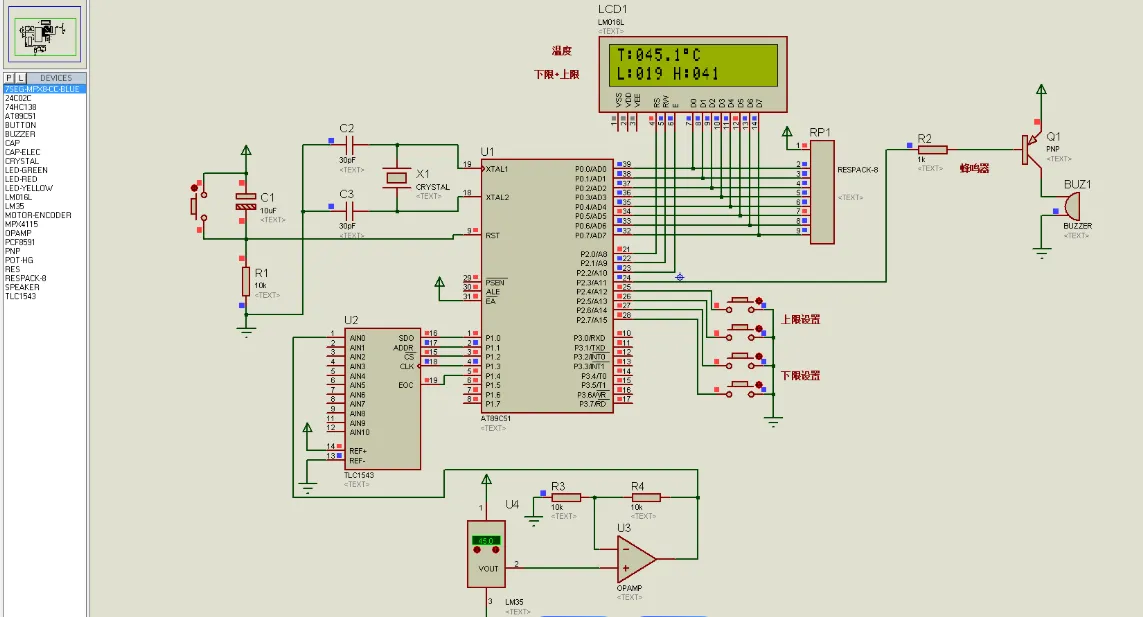
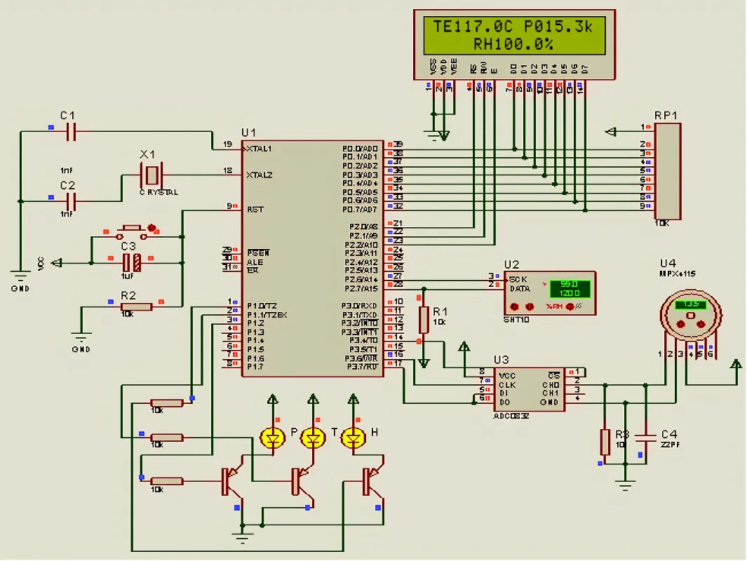
Step 2: Creating the Schematic for Your Weather Station
Now, let's build the schematic, which is a blueprint of your circuit. In your online design tool, open the schematic editor and start by adding components from the library. Search for the specific parts you planned, such as a microcontroller and sensors. If a component isn't available, most platforms allow you to create custom symbols or import them.
Place the components on the schematic canvas and connect them with wires. For example, connect the data pin of a temperature sensor to a digital input pin on your microcontroller. Ensure proper power connections, adding resistors or capacitors as needed for stability. A common practice is to place a 0.1μF decoupling capacitor near the power pins of integrated circuits to filter noise.
Label your connections (nets) for clarity, especially for power (VCC, GND) and data lines. Double-check the pin assignments against datasheets to avoid errors. For instance, connecting a sensor’s data pin to the wrong microcontroller pin could result in communication failure.
Step 3: Simulating Your Circuit Design
Many online PCB design tools offer simulation features to test your circuit before moving to the layout phase. Simulation helps identify issues like incorrect connections or voltage mismatches. Run a basic simulation to ensure signals flow correctly between components. For example, verify that the microcontroller can read data from the temperature sensor at the expected frequency (e.g., 1 Hz for periodic readings).
If the simulation shows errors, revisit your schematic to fix wiring or component values. This step saves time and prevents costly mistakes during manufacturing.
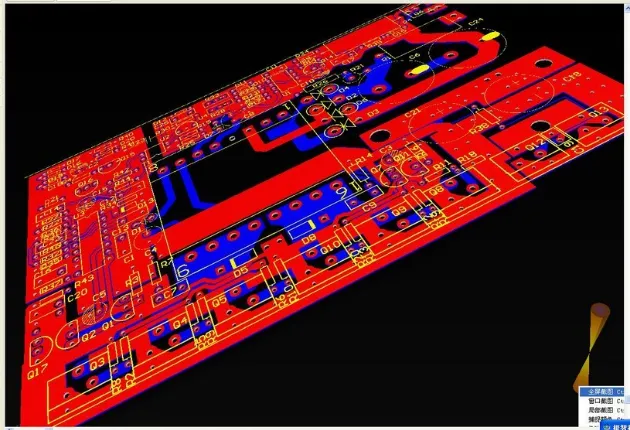
Step 4: Designing the PCB Layout
Once your schematic is ready and simulated, it's time to design the PCB layout. Switch to the layout editor in your online tool. Most platforms automatically transfer your schematic components to the layout area, where you arrange them on a virtual board.
Component Placement
Place components logically to minimize trace lengths and avoid interference. For a weather station PCB, group related components together—keep the microcontroller near the sensors to reduce signal delay. Place power-related components like voltage regulators near the board edge for easy access to power input.
Routing Traces
Route traces to connect components based on the schematic. Use a ground plane to reduce noise, especially for analog sensors that are sensitive to interference. Aim for trace widths that handle the expected current—for example, a 10-mil trace is suitable for low-current signal lines, while power traces may need 20-30 mils depending on the load (use online trace width calculators for precision).
Keep high-speed signals (if any) short and direct to avoid signal integrity issues. For instance, if your weather station uses I2C communication between the microcontroller and sensors, ensure clock and data lines are routed with equal lengths to prevent timing mismatches.
Design Rules Check (DRC)
Run a design rules check to ensure your layout meets manufacturing standards. This tool flags issues like overlapping traces or insufficient clearances. Typical clearance values are 6-8 mils between traces for standard manufacturing processes.
Step 5: Finalizing and Exporting Your Design
After completing the layout, review it for any missed connections or errors. Zoom in to check trace routing and component placement. Once satisfied, export the design files, typically in Gerber format, which manufacturers use to fabricate the PCB. Most online tools provide a "Generate Gerber" option under the file menu.
Additionally, export a Bill of Materials (BOM) listing all components with their specifications and quantities. This file helps during assembly and ensures you order the correct parts. Some platforms allow direct integration with manufacturing services, streamlining the process from design to production.
Step 6: Testing and Iterating
Once your PCB is manufactured and assembled, test it thoroughly. Power up the board and use a multimeter to check voltages at key points (e.g., ensure the microcontroller receives 3.3V or 5V as expected). Upload firmware to the microcontroller and verify that sensors provide accurate readings. For instance, compare the temperature sensor output to a known value to confirm calibration.
If issues arise—such as noise in sensor readings or communication failures—note the problems and revise your design. This might involve adjusting trace routing, adding filtering capacitors, or repositioning components. Iteration is a normal part of the design process, especially for complex projects like weather stations.
Tips for Optimizing Your Weather Station PCB Design
To make your weather station PCB more reliable and efficient, consider these tips:
- Compact Design: Minimize board size to reduce costs, but ensure enough space for heat dissipation if components like voltage regulators get hot.
- Environmental Protection: Since weather stations may be exposed to outdoor conditions, add conformal coating to protect against moisture and dust after assembly.
- Power Efficiency: Use low-power components and sleep modes in the microcontroller firmware to extend battery life if applicable.
- Modularity: Design with connectors for easy sensor replacement or upgrades.
Common Challenges and How to Overcome Them
Designing a PCB for a weather station can present challenges, especially for beginners. Here are some common issues and solutions:
- Signal Noise: Sensors can pick up interference. Use a ground plane and keep analog traces away from digital signals.
- Component Sourcing: Some parts may be hard to find. Check availability before finalizing your design, and have backup options.
- Thermal Issues: Components like microcontrollers can overheat. Add thermal vias or heat sinks if needed, and avoid tight clustering.
Conclusion: Bringing Your Weather Station to Life
Designing a PCB for a weather station using free online software is an accessible and fulfilling project. By following this tutorial, you've learned how to plan your circuit, create a schematic, simulate functionality, design a layout, and prepare files for manufacturing. With each step, you're closer to building a custom device that monitors environmental conditions tailored to your needs.
The beauty of using browser-based PCB design tools lies in their simplicity and cost-effectiveness. They empower hobbyists and professionals alike to experiment and innovate without breaking the bank. So, take the knowledge from this guide, start your design, and watch your weather station project come to life. With patience and practice, you'll master the art of PCB design and open doors to countless other electronics projects.


