 ALLPCB


Are you looking to build a DIY smart meter PCB to monitor your energy usage at home? This guide will walk you through the entire process of creating your own energy monitoring system, from designing a smart meter PCB schematic to programming the final product. Whether you're a hobbyist or an engineer, you'll find actionable steps for a successful DIY smart meter PCB project, including tips on schematic design, layout, component sourcing, and programming. Let's dive into the details of building a system that can help you track and manage your electricity consumption with precision.
Why Build a DIY Smart Meter PCB?
Smart meters are becoming essential tools for managing energy consumption in homes and small businesses. Unlike traditional meters, a smart meter provides real-time data on electricity usage, helping you identify inefficiencies and save on bills. While commercial smart meters are widely available, building your own DIY smart meter PCB project offers several advantages:
- Cost-Effective: Creating your own system can be cheaper than purchasing a pre-built device, especially if you already have some components.
- Customization: You can tailor the design and features to meet your specific needs, such as integrating with home automation systems.
- Learning Opportunity: Designing and assembling a smart meter PCB is a fantastic way to deepen your understanding of electronics and energy monitoring.
In this blog, we’ll cover every aspect of building a smart meter PCB, ensuring you have a clear roadmap to follow for your energy monitoring system.
Understanding the Basics of a Smart Meter PCB
Before starting your DIY smart meter PCB project, it’s important to understand what a smart meter does and the core components involved. A smart meter measures electrical parameters like voltage, current, and power consumption, then processes and displays or transmits this data for analysis.
The heart of any smart meter is its printed circuit board (PCB), which integrates sensors, microcontrollers, and communication modules. Here’s a quick breakdown of the key functionalities your PCB design should support:
- Measurement: Accurately capturing voltage and current data using sensors.
- Processing: Using a microcontroller to calculate power and energy usage.
- Communication: Transmitting data to a display or external system via Wi-Fi, Bluetooth, or other protocols.
- User Interface: Providing a way to view data, whether through an LCD screen or a smartphone app.
With these basics in mind, let’s move on to designing the smart meter PCB schematic, a critical step in your project.
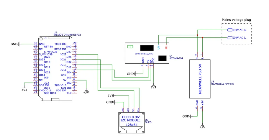
Step 1: Designing Your Smart Meter PCB Schematic
The smart meter PCB schematic is the blueprint of your project. It defines how components are connected and ensures that the system functions as intended. For a DIY smart meter PCB project, you’ll need to focus on a few key elements in your schematic design.
Key Components for the Schematic
Your schematic should include the following components:
- Current Sensor: A non-invasive current sensor, such as a current transformer (CT) with a burden resistor, to measure AC current safely. For example, a CT sensor with a 100A:50mA ratio can handle household loads effectively.
- Voltage Sensor: A voltage divider circuit or a dedicated voltage sensor module to measure AC voltage, typically stepping down 220V or 110V to a safe level (e.g., 5V) for the microcontroller.
- Microcontroller: A popular choice like the ESP32 or Arduino, which can process sensor data and handle communication. The ESP32, for instance, supports Wi-Fi, making it ideal for remote monitoring.
- Power Supply: A circuit to convert AC to DC (e.g., 5V or 3.3V) to power the microcontroller and other components. A 5V 1A power module can suffice for most designs.
- Communication Module: If not using an integrated solution like ESP32, you might add a separate Wi-Fi or Bluetooth module for data transmission.
- Display (Optional): An OLED or LCD screen to show real-time data locally, such as a 0.96-inch OLED with I2C communication.
Creating the Schematic
Use a free or open-source electronic design automation (EDA) tool to draw your smart meter PCB schematic. Start by placing the microcontroller at the center of your design, then connect the sensors, power supply, and communication modules. Ensure proper grounding to avoid noise in measurements, and add necessary resistors and capacitors for signal conditioning. For instance, a 10kΩ resistor in a voltage divider can help scale down high voltages for accurate readings.
Step 2: Crafting the Smart Meter PCB Layout
Once your schematic is ready, the next step in your DIY smart meter PCB project is designing the PCB layout. The smart meter PCB layout determines the physical placement of components and the routing of traces on the board, which impacts performance and safety.
Tips for an Effective PCB Layout
- Component Placement: Place high-voltage components (like those near the AC sensors) away from low-voltage sections to prevent interference. Keep the microcontroller near the communication and display modules for shorter signal paths.
- Trace Width: Use wider traces for high-current paths, especially near the power supply. For example, a trace carrying 1A at 5V should be at least 0.5mm wide to avoid overheating.
- Ground Plane: Include a solid ground plane to reduce noise and improve signal integrity, particularly important for accurate sensor readings.
- Isolation: Ensure proper isolation between AC and DC sections to maintain safety. A clearance of at least 3mm between high-voltage and low-voltage traces is recommended for household applications.
After completing the layout, double-check for errors like overlapping traces or unconnected pins. Most EDA tools offer design rule checks (DRC) to help identify issues before manufacturing.
Step 3: Smart Meter PCB Component Sourcing
Sourcing components for your DIY smart meter PCB project is a crucial step that affects both cost and performance. You’ll need to find reliable suppliers and ensure the components match your schematic specifications.
Where to Source Components
Look for components from trusted online marketplaces or local electronics stores. Popular platforms offer a wide range of sensors, microcontrollers, and other parts at competitive prices. Here are some tips for smart meter PCB component sourcing:
- Current and Voltage Sensors: Purchase CT sensors and voltage modules rated for your household’s electrical system (e.g., 100A for current and 250V for voltage).
- Microcontrollers: Opt for widely supported boards like the ESP32, which costs around $5–10 and has a large community for troubleshooting.
- Passive Components: Resistors, capacitors, and diodes can be bought in bulk for cost savings. For instance, a pack of 100 10kΩ resistors might cost less than $2.
- Power Supply Modules: Choose a module with overcurrent protection to safeguard your circuit, typically priced at $1–3 each.
Verifying Component Quality
Always check datasheets to confirm that components meet your design requirements. For example, ensure the current sensor’s output range (e.g., 0–5V) is compatible with your microcontroller’s analog input. Buying from reputable suppliers reduces the risk of receiving counterfeit or low-quality parts.
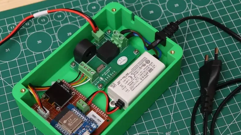
Step 4: Assembling Your Smart Meter PCB
With your PCB manufactured and components sourced, it’s time to assemble your smart meter PCB. This step requires basic soldering skills and attention to detail to avoid mistakes.
Assembly Tips
- Start with Small Components: Solder resistors, capacitors, and other small parts first, then move to larger components like sensors and microcontrollers.
- Check Polarity: Ensure correct orientation for polarized components like diodes and electrolytic capacitors to prevent damage.
- Test Connections: Use a multimeter to verify connections after soldering, checking for shorts or open circuits.
- Safety First: Since this project involves AC power, insulate exposed high-voltage areas with heat shrink tubing or electrical tape.
Once assembled, visually inspect the board for cold solder joints or misplaced components before powering it up.
Step 5: Smart Meter PCB Programming
Programming is the final step in bringing your DIY smart meter PCB project to life. The goal of smart meter PCB programming is to read sensor data, calculate energy usage, and transmit or display the results.
Programming Basics
If you’re using a microcontroller like the ESP32, you can program it using a platform like the Arduino IDE. Here’s a simplified workflow for smart meter PCB programming:
- Read Sensor Data: Write code to read analog signals from the current and voltage sensors. For example, use the ESP32’s ADC pins to capture voltage levels.
- Calculate Power: Multiply instantaneous voltage and current readings to compute power in watts. Integrate over time to calculate energy in watt-hours. A typical household might use 500W on average, so ensure your code handles such values accurately.
- Transmit Data: Use Wi-Fi libraries to send data to a cloud server or local app. Libraries like “ESPAsyncWebServer” can help set up a web interface for monitoring.
- Display Results: If using a local display, update the screen with real-time readings every few seconds using a library like “Adafruit_GFX” for OLED screens.
Sample Code Snippet
Here’s a basic example of reading sensor data with an ESP32:
const int currentPin = 34; // Analog pin for current sensor
const int voltagePin = 35; // Analog pin for voltage sensor

void setup() {
  Serial.begin(115200);
}

void loop() {
  int currentValue = analogRead(currentPin); // Read current sensor
  int voltageValue = analogRead(voltagePin); // Read voltage sensor
  float current = currentValue * (5.0 / 4095.0); // Convert to voltage
  float voltage = voltageValue * (5.0 / 4095.0);
  float power = current * voltage; // Calculate power
  Serial.print("Power: ");
  Serial.println(power);
  delay(1000);
}
This code provides a starting point. You’ll need to calibrate the readings based on your sensor specifications and add features like data logging or remote access.
Step 6: Testing and Calibration
After programming, test your smart meter PCB to ensure it works correctly. Connect it to a known load, such as a 100W bulb, and compare the readings with a reference meter. If discrepancies occur, adjust your code or sensor calibration factors. For instance, if your current sensor overreads by 5%, multiply the readings by 0.95 in your code to correct it.
Also, test the communication features. Verify that data is transmitted accurately to your app or server without delays. Ensure the system remains stable over long periods, as energy monitoring requires continuous operation.
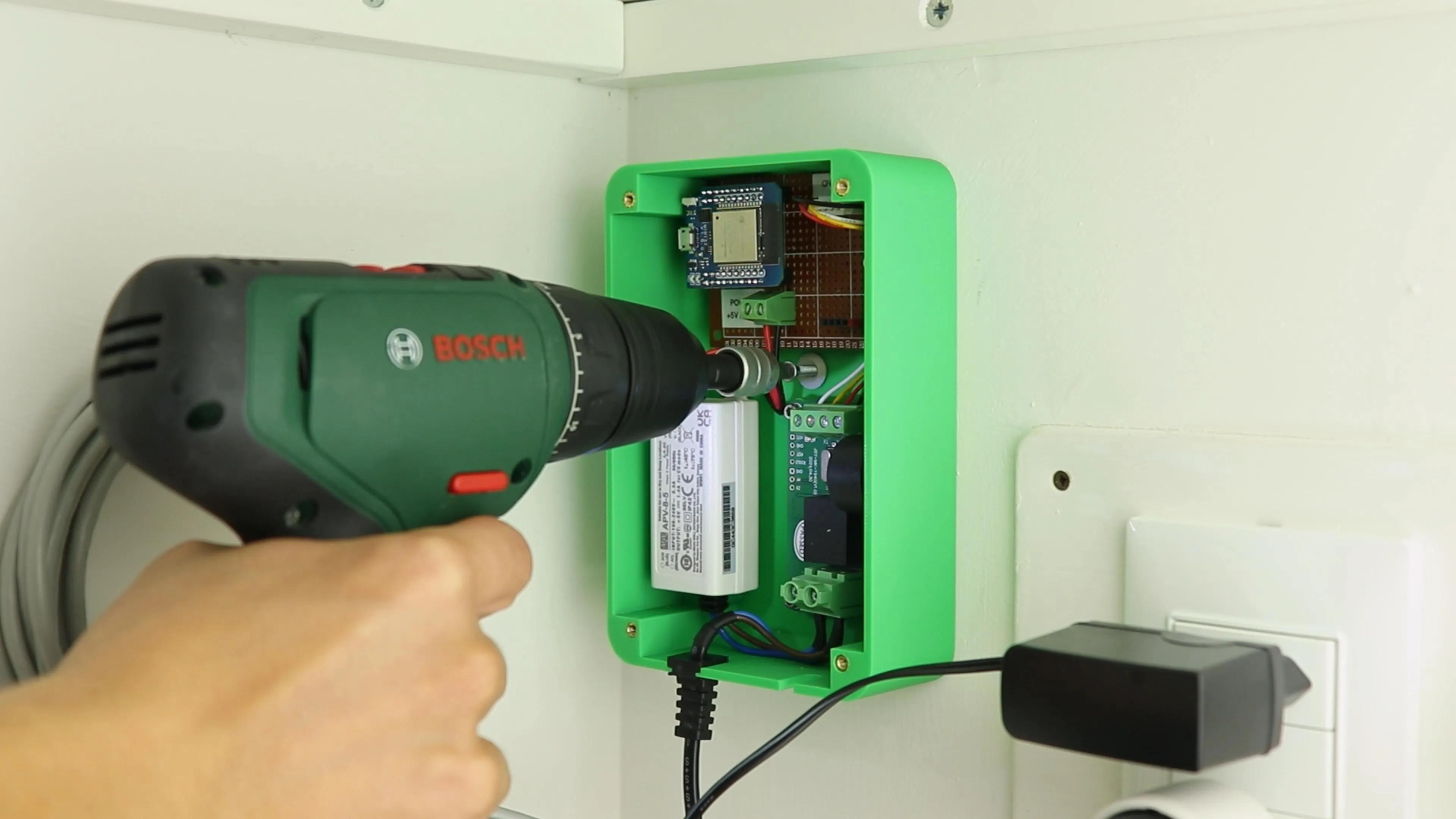
Step 7: Integration and Installation
Finally, integrate your DIY smart meter PCB into your home’s electrical system. Install it near your main power line using a non-invasive CT sensor clamped around the live wire. Secure the PCB in an enclosure to protect it from dust and accidental contact. If you’re not experienced with electrical installations, consult a professional to avoid safety hazards.
For a complete energy monitoring system, connect your smart meter to a home automation platform. This allows you to track usage patterns and set alerts for high consumption, maximizing the benefits of your project.
Conclusion
Building a DIY smart meter PCB is a rewarding project that combines electronics design, programming, and practical application. By following the steps outlined in this guide—designing a smart meter PCB schematic, creating an effective layout, sourcing components, assembling, programming, and testing—you can create a custom energy monitoring system tailored to your needs. Not only will you gain valuable skills, but you’ll also take control of your energy usage, potentially saving money in the long run.
With the right tools and dedication, your DIY smart meter PCB project can be a stepping stone to more advanced home automation solutions. Start small, test thoroughly, and enjoy the process of creating something both functional and innovative with the support of a trusted PCB manufacturing partner.


