ALLPCB


When designing RF circuits, selecting the right components for impedance matching networks is critical to ensure optimal signal transfer and minimize power loss. So, should you choose inductors or capacitors for your impedance matching network? The answer depends on your circuit's frequency, impedance requirements, and performance goals. In general, inductors are ideal for matching at lower frequencies or when blocking high-frequency noise, while capacitors excel at higher frequencies and filtering low-frequency signals. This blog dives deep into the nuances of impedance matching inductor selection, capacitor ESR impedance, and other key factors to help you make informed decisions for your RF designs.
Introduction to Impedance Matching in RF Circuits
Impedance matching is a fundamental concept in RF (radio frequency) circuit design. It involves adjusting the input or output impedance of a circuit to match the impedance of the connected load or source. When impedances are matched, maximum power transfer occurs, and signal reflections are minimized, leading to better efficiency and performance. Without proper matching, you risk signal loss, reduced efficiency, or even damage to sensitive components.
In RF circuits, impedance matching networks often use passive components like inductors and capacitors. These components form networks (such as L-networks or Pi-networks) to transform impedances to the desired value. But how do you decide between inductors and capacitors? Factors like frequency range, component tolerance, and quality factor (Q) play a significant role. Let’s explore these considerations in detail, targeting aspects like RF circuit component tolerance and high Q inductor for matching.
Why Impedance Matching Matters in RF Design
In RF circuits, mismatches in impedance can cause standing waves, signal distortion, and power loss. For instance, if a transmitter with an output impedance of 50 ohms is connected to an antenna with an impedance of 75 ohms without proper matching, a significant portion of the signal power will be reflected back to the transmitter, reducing efficiency. Proper impedance matching ensures that the power delivered from the source reaches the load with minimal loss, which is especially critical in high-frequency applications like wireless communication or radar systems.
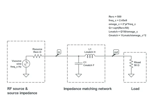
Impedance matching networks are typically designed to operate over a specific frequency band. The choice of components—inductors or capacitors—directly impacts the network’s performance across this band. Let’s break down the characteristics of each component to understand their roles in impedance matching network simulation and real-world applications.
Inductors in Impedance Matching Networks: Key Considerations
Inductors are often used in impedance matching networks, especially when dealing with lower frequencies or when you need to block high-frequency noise. Their ability to store energy in a magnetic field makes them ideal for certain RF applications. Here are some key factors to consider during impedance matching inductor selection.
1. Quality Factor (Q) and Performance
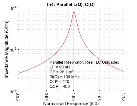
The quality factor, or Q, of an inductor measures its efficiency by comparing its inductive reactance to its resistance. A high Q inductor for matching is desirable because it minimizes energy loss and provides better selectivity in tuned circuits. For example, in a narrowband RF application operating at 100 MHz, selecting an inductor with a Q value of 50 or higher ensures minimal signal attenuation in the matching network.
2. Frequency Range and Self-Resonant Frequency (SRF)
Inductors have a self-resonant frequency (SRF), above which they behave more like capacitors due to parasitic capacitance. When selecting an inductor for RF circuits, ensure its SRF is well above your operating frequency. For instance, if your circuit operates at 1 GHz, choose an inductor with an SRF of at least 2 GHz to avoid performance degradation.
3. Tolerance and Stability
Inductors often have wider tolerance ranges compared to capacitors, typically ±5% to ±10%. This can impact the precision of your impedance matching network, especially in applications requiring tight control over impedance values. When addressing RF circuit component tolerance, always account for potential variations in inductor values and test the circuit across the tolerance range during simulation.
Capacitors in Impedance Matching Networks: Key Considerations
Capacitors are another cornerstone of impedance matching networks, particularly at higher frequencies where they can block low-frequency signals and pass high-frequency ones. Let’s explore their critical characteristics, including capacitor ESR impedance.
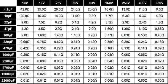
1. Equivalent Series Resistance (ESR) and Loss
Equivalent Series Resistance (ESR) is a measure of the internal resistance of a capacitor, which contributes to power loss and affects impedance at high frequencies. Low ESR capacitors are preferred in RF circuits to minimize losses. For example, in a 2.4 GHz Wi-Fi application, using a ceramic capacitor with an ESR of less than 0.1 ohms can significantly improve matching network efficiency.
2. Frequency Response and Dielectric Material
The performance of capacitors in RF circuits depends on their dielectric material. Ceramic capacitors, for instance, are widely used due to their low ESR and high stability at high frequencies. However, their capacitance can vary with temperature and voltage, which must be considered during design. For applications above 1 GHz, choose capacitors specifically rated for RF use to ensure consistent performance.
3. Tolerance and Precision
Capacitors generally offer tighter tolerance levels than inductors, often ±1% to ±5%. This makes them a better choice for applications where precise impedance matching is required. When factoring in RF circuit component tolerance, capacitors can provide more predictable results, especially in broadband matching networks.
Inductors vs. Capacitors: When to Use Each in RF Matching Networks
Choosing between inductors and capacitors for impedance matching depends on several factors, including the operating frequency, desired network topology, and performance requirements. Here’s a detailed comparison to guide your decision:
- Frequency Range: Inductors are typically used at lower frequencies (below 100 MHz) because their reactance increases with frequency, making them less effective at higher ranges. Capacitors, on the other hand, are ideal for higher frequencies (above 100 MHz) as their reactance decreases with frequency, allowing them to pass high-frequency signals effectively.
- Network Topology: Common impedance matching networks like L-networks often combine an inductor and a capacitor. For instance, to match a low-impedance source to a high-impedance load, you might use a series inductor followed by a shunt capacitor. The choice of which component to place where depends on the specific impedance transformation needed.
- Loss and Efficiency: Capacitors generally have lower losses (due to lower ESR) compared to inductors, making them preferable in high-frequency, low-loss applications. However, a high Q inductor for matching can outperform a capacitor in specific tuned circuits where selectivity is critical.
Simulating Impedance Matching Networks for Optimal Component Selection
Before finalizing your component choices, simulating the impedance matching network is essential to predict performance and identify potential issues. Impedance matching network simulation tools allow you to model the behavior of inductors and capacitors under different conditions, ensuring your design meets the desired specifications.
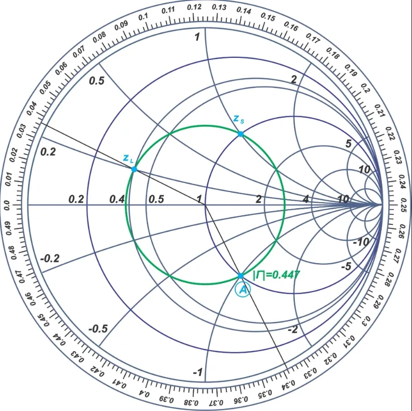
1. Use Smith Charts for Visualization
A Smith Chart is a powerful tool for visualizing impedance matching. It helps you plot the impedance of your circuit and determine the required values of inductors and capacitors to achieve a match. For example, if your source impedance is 50 ohms and your load is 100 + j50 ohms at 500 MHz, the Smith Chart can guide you to add a series capacitor of approximately 3 pF to move the impedance toward the center (50 ohms).
2. Account for Parasitic Effects
During simulation, include parasitic effects such as inductor capacitance and capacitor inductance. These parasitics can significantly alter the behavior of your network at high frequencies. For instance, a 10 nH inductor might have a parasitic capacitance of 0.5 pF, causing resonance at around 2 GHz, which could interfere with your design if not accounted for.
3. Test Across Frequency Bands
Simulate your network across the entire operating frequency band to ensure consistent performance. A matching network designed for 900 MHz might work perfectly at that frequency but fail at 850 MHz if component tolerances or parasitics are not considered. Use simulation software to sweep frequencies and observe changes in S-parameters like S11 (return loss) to validate your design.
Practical Tips for Component Selection in RF Impedance Matching
To wrap up, here are some actionable tips to guide your component selection process for impedance matching networks in RF circuits:
- Prioritize Low-Loss Components: Choose inductors with high Q values and capacitors with low ESR to minimize losses, especially in high-frequency designs.
- Check Component Ratings: Ensure that the selected components can handle the power levels and frequencies of your application. For example, a capacitor rated for 50V might fail in a high-power RF circuit transmitting at 100W.
- Consider Temperature Stability: RF circuits often operate in varying environmental conditions. Select components with stable performance over temperature ranges to avoid impedance drift.
- Validate with Prototypes: After simulation, build and test a prototype to confirm that the selected components achieve the desired matching. Measure parameters like return loss and insertion loss to fine-tune your design.
Conclusion: Making the Right Choice for Your RF Circuit
Selecting the right components for impedance matching networks in RF circuits is a balance of technical requirements and practical constraints. Inductors shine in lower-frequency applications and when high selectivity is needed, while capacitors are the go-to choice for high-frequency designs with low loss. By considering factors like impedance matching inductor selection, capacitor ESR impedance, and RF circuit component tolerance, you can design efficient and reliable matching networks. Additionally, leveraging tools for impedance matching network simulation ensures that your choices are validated before implementation.
Whether you’re working on a wireless communication system, a radar module, or any other RF application, understanding the strengths and limitations of inductors and capacitors is key to achieving optimal performance. With the right components and a thorough design process, you can ensure maximum power transfer and minimal signal loss in your RF circuits.