Understanding how to calculate PCB board power is crucial for designing efficient and reliable electronic systems. Whether you're an engineer working on a new project or a hobbyist building a custom circuit, knowing the power requirements in watts, the role of components, and the impact of voltage on your electronic PCB can prevent failures and optimize performance. Additionally, managing heat generation is key to ensuring longevity and safety. In this detailed guide, we'll walk you through the essentials of calculating PCB board power and provide actionable insights to help you succeed.
Why Calculating PCB Board Power Matters
Power calculation for an electronic PCB is the foundation of a successful design. It determines how much energy your board consumes, helps you choose the right power supply, and ensures that components operate within safe limits. Overlooking power requirements can lead to overheating, component damage, or system failure. By calculating power in watts, considering voltage levels, and understanding heat generation, you can design a PCB that performs reliably under various conditions.

Key Concepts in PCB Power Calculation
Before diving into the step-by-step process, let’s clarify some fundamental concepts related to power, watts, voltage, components, and heat generation in an electronic PCB.
What Is Power in an Electronic PCB?
Power, measured in watts (W), represents the rate at which electrical energy is consumed or dissipated in a circuit. On a PCB, power is distributed among components like resistors, capacitors, integrated circuits (ICs), and other elements. The basic formula for power is:
Power (P) = Voltage (V) × Current (I)
Here, voltage is measured in volts (V), and current is measured in amperes (A). This formula is the starting point for calculating the total power consumption of your PCB board.
Role of Voltage in Power Calculation
Voltage is the electrical potential difference that drives current through the components on your PCB. Most electronic PCBs operate at specific voltage levels, such as 3.3V, 5V, or 12V, depending on the components used. Knowing the operating voltage of each component is essential because it directly impacts the power consumed. For instance, a component operating at 5V with a current draw of 0.2A consumes 1 watt of power (5V × 0.2A = 1W).
Components and Their Power Consumption
Different components on an electronic PCB consume varying amounts of power. For example:
- Resistors: Dissipate power as heat, calculated using P = I2 × R, where R is resistance in ohms (Ω).
- ICs and Microcontrollers: Often have specified power consumption in datasheets, typically in milliwatts (mW) or watts (W).
- LEDs: Consume power based on their forward voltage and current, often around 0.06W per LED for standard types (e.g., 3V × 0.02A).
Each component contributes to the total power budget of the PCB, so accounting for every element is critical.
Heat Generation in PCBs
When power is consumed or dissipated, it often converts into heat. Excessive heat generation can damage components or degrade performance. For instance, a resistor dissipating 2W of power as heat might raise the local temperature significantly if not managed properly. Heat dissipation techniques, such as using thermal vias or heat sinks, are vital for high-power designs.

Step-by-Step Guide to Calculating PCB Board Power
Now that we’ve covered the basics, let’s walk through a practical approach to calculating the power consumption of your electronic PCB. Follow these steps to ensure accuracy and reliability in your design.
Step 1: List All Components and Their Specifications
Start by creating a detailed list of every component on your PCB. Refer to datasheets or manufacturer specifications to note the operating voltage and current draw for each. For example:
- Microcontroller: 3.3V, 0.05A (0.165W)
- LEDs (5 units): 2V, 0.02A each (0.04W per LED, total 0.2W)
- Resistors (2 units): 0.5A through 10Ω each (2.5W per resistor, total 5W)
This inventory helps you understand the power needs of individual elements before summing them up.
Step 2: Calculate Power for Each Component
Using the power formula P = V × I, calculate the power consumption for components with known voltage and current. For resistors, use P = I2 × R if current and resistance are provided. Add up the values to get a subtotal for each type of component. Continuing the example above:
- Microcontroller: 0.165W
- LEDs: 0.2W
- Resistors: 5W
- Total Power: 0.165W + 0.2W + 5W = 5.365W
Step 3: Account for Efficiency Losses
Not all power supplied to a PCB is used by components; some is lost as heat or inefficiency in power conversion (e.g., through voltage regulators). A common efficiency factor for DC-DC converters is around 80-90%. If your PCB uses a regulator with 85% efficiency, the actual power drawn from the supply would be higher:
Adjusted Power = Total Power / Efficiency = 5.365W / 0.85 = 6.31W
This adjusted value represents the power your supply must provide.
Step 4: Consider Voltage Domains
Many PCBs operate with multiple voltage levels (e.g., 3.3V for logic, 12V for motors). Calculate power separately for each voltage domain and sum the results. For instance, if you have 3.3V components consuming 2W and 12V components consuming 4W, the total power is 6W, but you’ll need separate power supplies or regulators for each domain.
Step 5: Evaluate Heat Generation and Dissipation
Once you know the total power in watts, estimate how much of it will turn into heat. Components like resistors and power ICs often dissipate most of their power as heat. For example, if your PCB consumes 6.31W and 4W of that is from resistive losses, you’ll need to manage that heat through proper layout, thermal vias, or cooling solutions. A general rule of thumb is that 1W of power dissipation can raise the temperature of a small area by 10-20°C without adequate cooling.

Factors Affecting PCB Power Consumption
Several factors influence the power consumption of an electronic PCB beyond just components and voltage. Understanding these can help you optimize your design.
Operating Frequency
High-frequency operations, such as those in microcontrollers or RF circuits, increase power consumption due to switching losses. For example, a microcontroller running at 100MHz may consume 50% more power than one at 50MHz, even if other parameters remain the same.
Ambient Temperature
Higher ambient temperatures can increase power dissipation as components work harder to maintain performance. A PCB operating in a 40°C environment might consume 10-15% more power than one at 25°C due to increased leakage currents in semiconductors.
Power Supply Design
The choice of power supply or regulator impacts overall efficiency. Linear regulators often have lower efficiency (50-60%) compared to switching regulators (80-95%), leading to higher power losses and heat generation.
Tips for Managing Power and Heat in PCB Design
Effective power management goes hand-in-hand with heat control. Here are some practical tips to keep your electronic PCB running smoothly.
Use Power-Efficient Components
Opt for low-power versions of components when possible. For example, choose a microcontroller with a low-power mode that reduces consumption to microamps during idle states.
Optimize PCB Layout
Place high-power components away from sensitive areas and ensure adequate spacing for airflow. Use wider traces for power lines to reduce resistance and heat buildup. For instance, a trace carrying 2A of current should be at least 0.5mm wide for a 1oz copper layer to minimize voltage drop and heating.
Incorporate Heat Dissipation Techniques
Add thermal vias under high-power components to transfer heat to other layers or a heat sink. For a component dissipating 3W, placing 4-6 thermal vias (0.3mm diameter each) can reduce local temperature by 5-10°C.
Monitor and Test
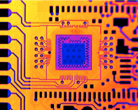
After assembling your PCB, use a multimeter to measure actual current draw and compare it with your calculations. Use thermal imaging to identify hotspots and address them before they cause issues.
Common Mistakes to Avoid When Calculating PCB Power
Even experienced designers can make errors in power calculation. Here are some pitfalls to watch out for:
- Ignoring Idle or Standby Power: Some components consume power even when not active. Always check datasheets for standby current.
- Underestimating Heat: Failing to account for heat generation can lead to thermal runaway, where components overheat and fail.
- Overlooking Voltage Drops: Long traces or poor connections can cause voltage drops, reducing the actual voltage at components and affecting performance.
Conclusion: Mastering PCB Power Calculation
Calculating PCB board power is a critical skill for anyone involved in electronic design. By understanding the interplay of watts, components, voltage, and heat generation, you can create efficient and reliable electronic PCBs that meet your project’s needs. Start with a detailed inventory of components, calculate power for each, adjust for efficiency losses, and design with heat management in mind. With these steps, you’ll ensure your PCB operates safely and performs at its best.
Whether you’re working on a small hobby project or a complex industrial system, accurate power calculation is the key to success. Use the guidelines and tips provided in this guide to refine your approach and build better designs. For professional support in PCB manufacturing and assembly, trust a reliable partner to bring your ideas to life with precision and quality.
 ALLPCB


