ALLPCB


Are you looking to optimize your audio amplifier PCB SMT assembly process? Surface Mount Technology (SMT) is a game-changer for creating compact, high-performance audio amplifiers, but it demands precision and adherence to best practices. In this comprehensive guide, we’ll explore the essentials of audio amplifier PCB assembly, focusing on key areas like reflow soldering, component placement, automated optical inspection (AOI), and automated assembly. Whether you’re an engineer or a manufacturer, these tips will help you achieve reliable, high-quality results.
At ALLPCB, we understand the importance of precision in electronics manufacturing. Let’s dive into the best practices for SMT assembly tailored specifically for audio amplifiers, ensuring optimal performance and durability.
Why Surface Mount Technology for Audio Amplifier PCBs?
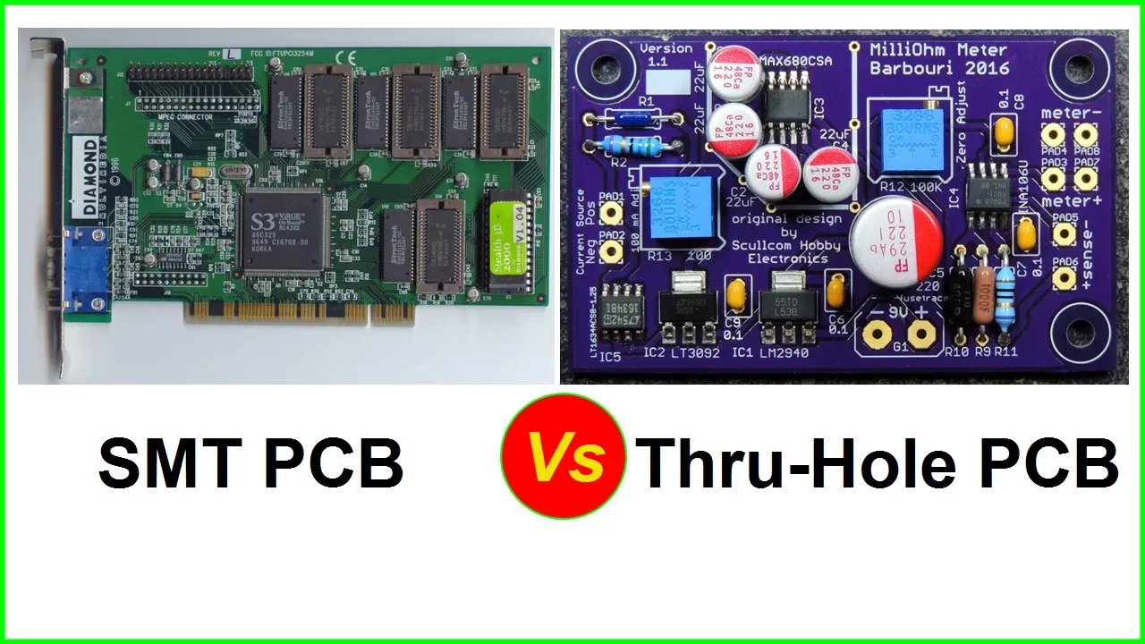
Surface Mount Technology has become the standard for assembling audio amplifier PCBs due to its numerous advantages. Unlike traditional through-hole methods, SMT allows for smaller components, higher circuit density, and faster production. This is critical for audio amplifiers, where space-saving designs and signal integrity are paramount. With SMT, you can place components on both sides of the PCB, achieving a compact layout without compromising performance.
For audio amplifiers, SMT also supports better high-frequency performance. Smaller components reduce parasitic capacitance and inductance, which can interfere with audio signals. This results in clearer sound and less noise, making SMT ideal for modern audio applications.
Key Steps in Audio Amplifier PCB SMT Assembly
The SMT assembly process for audio amplifier PCBs involves several critical steps. Each stage, from design to final inspection, plays a vital role in ensuring the quality and functionality of the final product. Let’s break down these steps with a focus on best practices.
1. PCB Design Optimization for Audio Amplifiers
Before assembly begins, a well-thought-out PCB design is essential. For audio amplifiers, the layout must minimize signal interference and ensure proper power distribution. Keep signal paths short to reduce noise, and separate analog and digital grounds to prevent crosstalk. Additionally, place decoupling capacitors close to power pins of ICs to stabilize voltage and reduce ripple, which can affect audio quality.
Ensure that high-current traces, such as those connected to power amplifiers, are wide enough to handle the load. For example, a trace carrying 2A of current might need a width of at least 40 mils at 1 oz copper thickness to avoid overheating. Use design software with simulation tools to test for signal integrity and thermal performance before moving to production.
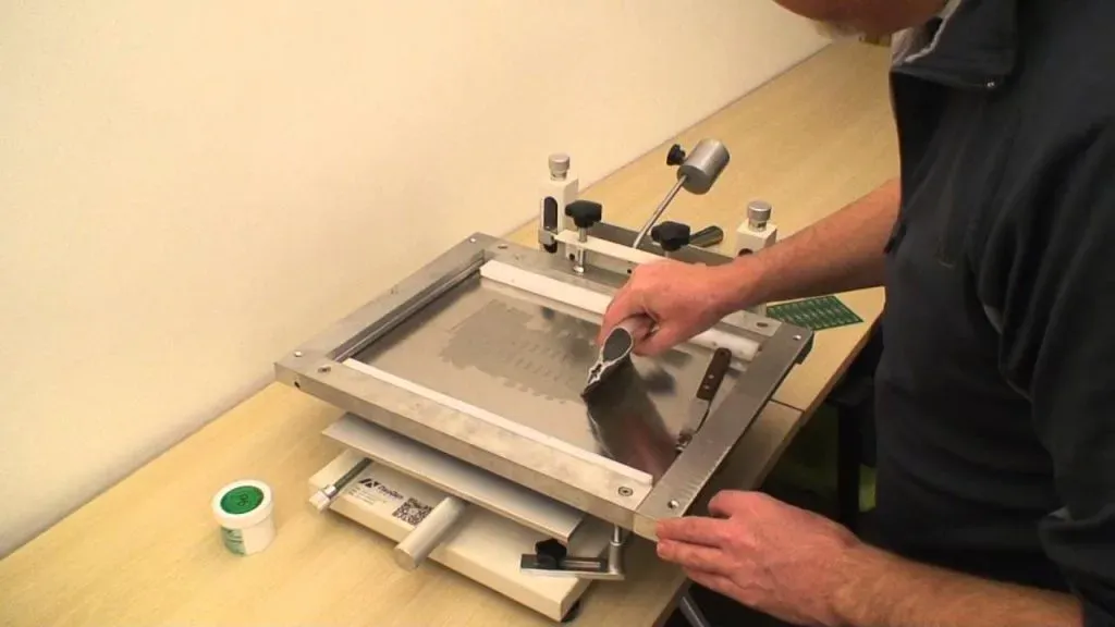
2. Solder Paste Application for Precision
The first step in SMT assembly is applying solder paste to the PCB. Use a stencil to ensure accurate placement of paste on the pads where components will be mounted. For audio amplifier PCBs, precision is critical because even a small misalignment can lead to poor connections, affecting sound quality or causing circuit failure.
Choose a high-quality solder paste with the right alloy composition, such as SAC305 (96.5% tin, 3% silver, 0.5% copper), which offers excellent reliability for SMT applications. Maintain consistent stencil thickness—typically 4 to 5 mils for fine-pitch components—to avoid excess or insufficient paste.
3. Component Placement: Accuracy and Efficiency
Component placement is a critical stage in audio amplifier PCB SMT assembly. Automated pick-and-place machines are used to position surface-mount components with high precision. For audio amplifiers, ensure that sensitive components like op-amps and capacitors are placed away from heat-generating parts to prevent thermal stress, which can degrade performance over time.
Pay attention to the orientation of polarized components, such as electrolytic capacitors, to avoid reverse polarity issues. Additionally, follow the manufacturer’s footprint guidelines for ICs and connectors to ensure proper alignment during reflow soldering. Modern pick-and-place machines can achieve placement speeds of over 100,000 components per hour, making automated assembly both fast and reliable for large-scale production.
4. Reflow Soldering: Achieving Strong Connections
Reflow soldering is the process of melting solder paste to form permanent connections between components and the PCB. For audio amplifier PCBs, a well-controlled reflow profile is essential to prevent issues like cold solder joints or component damage. The reflow process typically involves four stages: preheat, soak, reflow, and cooling.
During the preheat stage, gradually increase the temperature to around 150°C over 60-90 seconds to activate the flux in the solder paste. In the soak stage, maintain a temperature of 150-180°C for about 60 seconds to ensure even heating. The reflow stage peaks at around 240-250°C for 20-30 seconds, melting the solder to form strong bonds. Finally, cool the board at a controlled rate to avoid thermal shock, which can crack components or warp the PCB.
For audio amplifiers, monitor the reflow profile closely, especially for components with tight thermal tolerances. Use a reflow oven with multiple zones to achieve precise temperature control. Improper soldering can lead to signal distortion or intermittent connections, directly impacting audio performance.

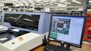
5. Automated Optical Inspection (AOI) for Quality Assurance
After reflow soldering, Automated Optical Inspection (AOI) is used to detect defects in the assembly. AOI systems use high-resolution cameras and advanced algorithms to check for issues like misaligned components, insufficient solder, or bridging. For audio amplifier PCBs, where even minor defects can cause noise or signal loss, AOI is a critical step in ensuring quality.
AOI can inspect thousands of components per minute, identifying defects with over 99% accuracy. This technology is especially useful for fine-pitch components and densely populated boards common in audio amplifiers. If defects are found, the board can be sent for rework before proceeding to functional testing.
6. Functional Testing and Final Assembly
Once the PCB passes inspection, it undergoes functional testing to verify performance. For audio amplifiers, this includes testing for output power, frequency response, and total harmonic distortion (THD). For example, a Class D amplifier might be tested to ensure it delivers a THD of less than 0.1% at rated power, which is crucial for high-fidelity audio.
After testing, the PCB may be integrated into a larger assembly with enclosures, connectors, and heat sinks. Ensure that all connections are secure and that thermal management solutions are in place to handle the heat generated by power components during operation.
Best Practices for Audio Amplifier PCB SMT Assembly
Beyond the basic steps, adopting specific best practices can elevate the quality of your audio amplifier PCB assembly. These tips focus on optimizing performance, reducing errors, and ensuring long-term reliability.
Minimize Noise Through Grounding and Shielding
Audio amplifiers are highly sensitive to electrical noise, which can degrade sound quality. Use a solid ground plane to provide a low-impedance path for return currents, reducing electromagnetic interference (EMI). If possible, implement shielding around sensitive analog sections to block external noise sources. Proper grounding can reduce noise levels by up to 20 dB, significantly improving audio clarity.
Choose Components Wisely
Select components that match the performance requirements of your audio amplifier. For instance, use low-noise op-amps with a noise density of less than 5 nV/√Hz for preamplifier stages. Similarly, choose capacitors with low equivalent series resistance (ESR) to minimize signal loss in filtering circuits. Always source components from reputable suppliers to avoid counterfeit parts that could fail prematurely.
Optimize Thermal Management
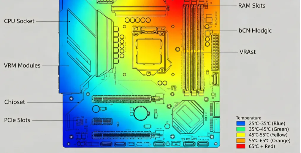
Audio amplifiers often generate significant heat, especially in high-power applications. Place heat-generating components like power transistors or ICs in areas with good airflow or near heat sinks. Use thermal vias under components to transfer heat to the opposite side of the PCB. Effective thermal management can extend the lifespan of components by maintaining operating temperatures below 85°C, even under full load.
Leverage Automated Assembly for Consistency
Automated assembly is a cornerstone of modern SMT production. By using automated pick-and-place machines and AOI systems, you can achieve consistent results across high-volume runs. Automation reduces human error, ensuring that every audio amplifier PCB meets the same high standards. This is especially important for maintaining brand reputation in competitive markets.
Common Challenges in Audio Amplifier PCB SMT Assembly
Despite the advantages of SMT, certain challenges can arise during assembly. Being aware of these issues and knowing how to address them can save time and resources.
Component Misalignment: Misaligned components can lead to poor connections or short circuits. Use high-precision pick-and-place machines and double-check stencil alignment to avoid this issue.
Thermal Stress: Excessive heat during reflow soldering can damage sensitive components. Follow recommended thermal profiles and use components rated for SMT processes to minimize risks.
Solder Bridging: Excess solder can create bridges between pads, causing shorts. Optimize solder paste volume and inspect boards with AOI to catch bridging early.
Why Partner with ALLPCB for Audio Amplifier PCB Assembly?
At ALLPCB, we specialize in delivering high-quality SMT assembly services tailored to the unique needs of audio amplifier production. Our state-of-the-art facilities are equipped with advanced automated assembly lines, multi-zone reflow ovens, and cutting-edge AOI systems to ensure precision at every step. We understand the importance of signal integrity and thermal management in audio applications, and our team of experts is committed to helping you achieve superior results.
From prototype to mass production, we offer end-to-end solutions that streamline your manufacturing process. With a focus on quality, speed, and cost-efficiency, we’re your trusted partner for audio amplifier PCB SMT assembly.
Conclusion
Assembling audio amplifier PCBs using Surface Mount Technology requires careful attention to detail, from design and component placement to reflow soldering and inspection. By following the best practices outlined in this guide, such as optimizing layouts for signal integrity, using automated assembly for precision, and leveraging AOI for quality control, you can produce high-performance audio amplifiers that meet the demands of modern applications.
Whether you’re tackling noise issues, thermal challenges, or production scalability, the right approach to SMT assembly can make all the difference. At ALLPCB, we’re here to support you with expertise and advanced manufacturing capabilities. Let’s work together to bring your audio amplifier designs to life with unparalleled quality and efficiency.