 ALLPCB


If you're diving into PCB design, one of the most critical decisions you'll make is choosing the right connectors. Whether you're looking for PCB connector types, a connector selection guide, or specifics on board-to-board connectors, wire-to-board connectors, or RF connectors, this guide has you covered. We'll break down the essentials of each connector type, their applications, and tips for selecting the best option for your project. Let's explore everything you need to know to ensure reliable and efficient connections in your printed circuit board designs.
Why Connectors Matter in PCB Design
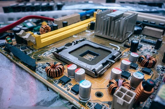
Connectors are the unsung heroes of PCB design. They create the vital links between components, boards, and external devices, ensuring seamless transmission of power, signals, and data. A poorly chosen connector can lead to signal loss, mechanical failure, or even complete system breakdowns. On the other hand, the right connector enhances performance, durability, and ease of assembly. With countless options available, understanding PCB connector types and their specific uses is the first step to a successful design.
What Are the Main Types of PCB Connectors?
PCB connectors come in various shapes, sizes, and configurations, each tailored for specific functions. Below, we’ll explore the most common types, focusing on their structure, purpose, and typical applications.
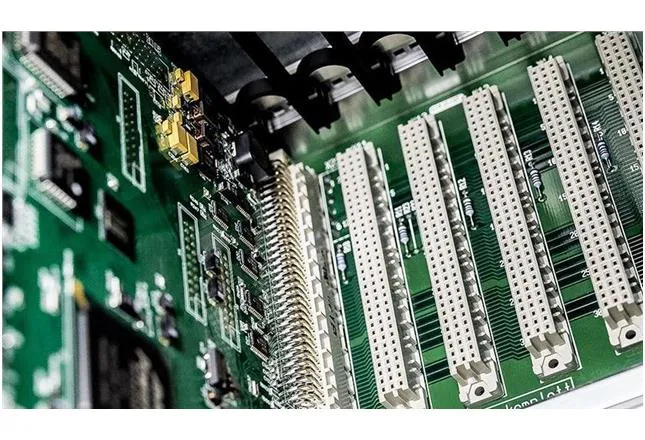
1. Board-to-Board Connectors
Board-to-board connectors are designed to link two PCBs together, often used in compact devices where space is limited. These connectors allow for direct communication between boards without the need for external wiring, reducing clutter and improving reliability.
- Key Features: Available in pin headers, sockets, and mezzanine styles. They often support high-density connections with pitch sizes as small as 0.4mm.
- Applications: Found in smartphones, tablets, and multi-board systems where stacking is necessary.
- Advantages: Compact design, high signal integrity, and support for high-speed data transfer (up to 10 Gbps in some cases).
- Considerations: Ensure proper alignment during assembly to avoid connection issues. Mating cycles (typically 10 to 100) should match the expected usage.
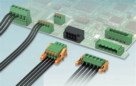
2. Wire-to-Board Connectors
Wire-to-board connectors facilitate connections between a wire or cable and a PCB. They are essential for bringing external power or signals into the board and are widely used across industries.
- Key Features: Often feature crimp terminals or insulation displacement contacts (IDC). Available in pitches ranging from 1.0mm to 5.08mm.
- Applications: Common in automotive systems, home appliances, and industrial equipment.
- Advantages: Easy to install and replace, with secure locking mechanisms to prevent disconnection.
- Considerations: Pay attention to current and voltage ratings (e.g., some handle up to 10A at 250V) to match your circuit's requirements.
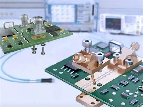
3. RF Connectors
RF (Radio Frequency) connectors are specialized for high-frequency signals, typically in the range of 3 kHz to 300 GHz. They are built to maintain signal integrity with minimal loss or interference, making them crucial for communication devices.
- Key Features: Designed with controlled impedance (often 50 ohms or 75 ohms) to prevent signal reflection. Common types include SMA, BNC, and MCX connectors.
- Applications: Used in wireless devices, antennas, GPS modules, and test equipment.
- Advantages: Low signal loss and high-frequency performance (some support up to 18 GHz).
- Considerations: Choose connectors with proper shielding to avoid electromagnetic interference (EMI). Mating durability (often 500 cycles for SMA types) is also a factor.
4. Other Notable PCB Connector Types
Beyond the primary categories, several other connectors play vital roles in PCB design:
- Wire-to-Wire Connectors: Used to join two sets of wires without involving a PCB, often in power distribution systems.
- Edge Connectors: Found in plug-in cards, these connect directly to the edge of a PCB, common in older computer hardware with mating cycles around 25-50.
- Power Connectors: Designed for high-current applications, supporting up to 40A in some industrial setups.
A Connector Selection Guide for PCB Design
Selecting the right connector for your PCB design can feel overwhelming with so many options. However, focusing on a few key factors can simplify the process. This connector selection guide will help you make informed decisions tailored to your project needs.
1. Understand Your Electrical Requirements
Start by evaluating the electrical demands of your circuit:
- Current and Voltage: Ensure the connector can handle the required load. For example, a power connector for industrial use might need to support 20A at 600V, while a signal connector may only need 1A at 5V.
- Signal Type: For high-speed data or RF signals, prioritize connectors with low impedance mismatch and minimal insertion loss (e.g., under 0.5 dB for RF connectors).
- Frequency Range: RF connectors must match the frequency of your application. A connector rated for 6 GHz won’t perform well in a 12 GHz system.
2. Consider Mechanical Constraints
The physical aspects of your design also influence connector choice:
- Size and Pitch: In compact designs, opt for connectors with smaller pitches (e.g., 0.5mm for board-to-board connectors) to save space.
- Mating Cycles: If frequent connections and disconnections are expected, choose a connector with a high mating cycle rating (e.g., 100 cycles for wire-to-board connectors).
- Mounting Type: Decide between through-hole or surface-mount connectors based on your PCB assembly process. Surface-mount options are often preferred for automated production.
3. Evaluate Environmental Factors
The operating environment can impact connector performance:
- Temperature Range: Some connectors are rated for extreme conditions, such as -40°C to 105°C, ideal for automotive or outdoor applications.
- Moisture and Dust: For harsh environments, look for connectors with IP ratings (e.g., IP67 for waterproofing) to ensure reliability.
- Vibration and Shock: In applications like aerospace, connectors with locking mechanisms or rugged designs prevent disconnection under stress.
4. Budget and Availability
Cost and supply chain factors are practical considerations. High-performance connectors, such as those for RF applications, often come with a higher price tag (sometimes $5-$10 per unit compared to $0.50 for basic headers). Balance performance needs with budget constraints, and ensure the chosen connector is readily available to avoid production delays.
Suggested Reading: The Ultimate Guide to Selecting the Right Connectors for Your PCB Components
Best Practices for Integrating Connectors in PCB Design
Choosing the right connector is only part of the equation. Proper integration into your PCB layout is equally important for performance and reliability. Here are some best practices to follow:
- Optimize Placement: Position connectors near the edge of the board for easy access, especially for wire-to-board types. For board-to-board connectors, ensure alignment with mating boards.
- Minimize Signal Interference: For RF connectors, keep traces short and use ground planes to reduce EMI. Maintain a 50-ohm impedance path if possible.
- Secure Mechanical Stability: Use mounting holes or brackets for connectors under mechanical stress. This is crucial for heavy-duty power connectors handling currents above 10A.
- Test Thoroughly: Simulate your design under real-world conditions to check for signal integrity, thermal performance, and mechanical durability before production.
Common Challenges with PCB Connectors and How to Avoid Them
Even with careful planning, connector-related issues can arise. Here are some common challenges and tips to mitigate them:
- Signal Loss in RF Applications: Use connectors with low insertion loss and ensure proper impedance matching. Avoid sharp bends in traces near RF connectors.
- Mechanical Failure: Over-mating or misalignment can damage connectors. Choose designs with guiding features or higher mating cycle ratings for frequent use.
- Thermal Overload: High-current connectors can overheat if undersized. Select connectors with adequate current ratings and consider heat dissipation in your layout.
Future Trends in PCB Connector Technology
The world of PCB connectors is evolving rapidly to meet the demands of modern electronics. Here are a few trends to watch:
- Miniaturization: As devices shrink, connectors with pitches below 0.3mm are becoming more common, especially in wearables and IoT devices.
- High-Speed Data: Connectors supporting data rates above 25 Gbps are emerging to handle next-generation communication standards like 5G.
- Sustainability: Manufacturers are focusing on eco-friendly materials and designs that reduce waste during production and disposal.
Conclusion: Mastering Connector Selection for PCB Success
Understanding PCB connector types and following a solid connector selection guide are foundational to creating reliable and efficient printed circuit board designs. Whether you're working with board-to-board connectors for compact systems, wire-to-board connectors for power delivery, or RF connectors for high-frequency signals, each type has unique benefits and considerations. By carefully assessing electrical, mechanical, and environmental needs, you can choose connectors that enhance your project's performance and longevity.
At ALLPCB, we’re committed to supporting your design journey with resources and expertise. Keep these insights in mind as you tackle your next PCB project, and you’ll be well on your way to building robust, high-performing electronics.


