 ALLPCB


Are you struggling with a malfunctioning microprocessor PCB and unsure where to start? Troubleshooting microprocessor PCBs can be challenging, but with the right approach, you can identify and fix issues like power failures, signal integrity problems, and component defects. In this practical guide, we’ll walk you through proven techniques for microprocessor PCB troubleshooting, PCB failure analysis, and diagnosing microprocessor issues. Whether you're dealing with common PCB problems or need effective PCB repair techniques, this post will equip you with the knowledge to get your circuit board back on track.
Why Microprocessor PCB Troubleshooting Matters
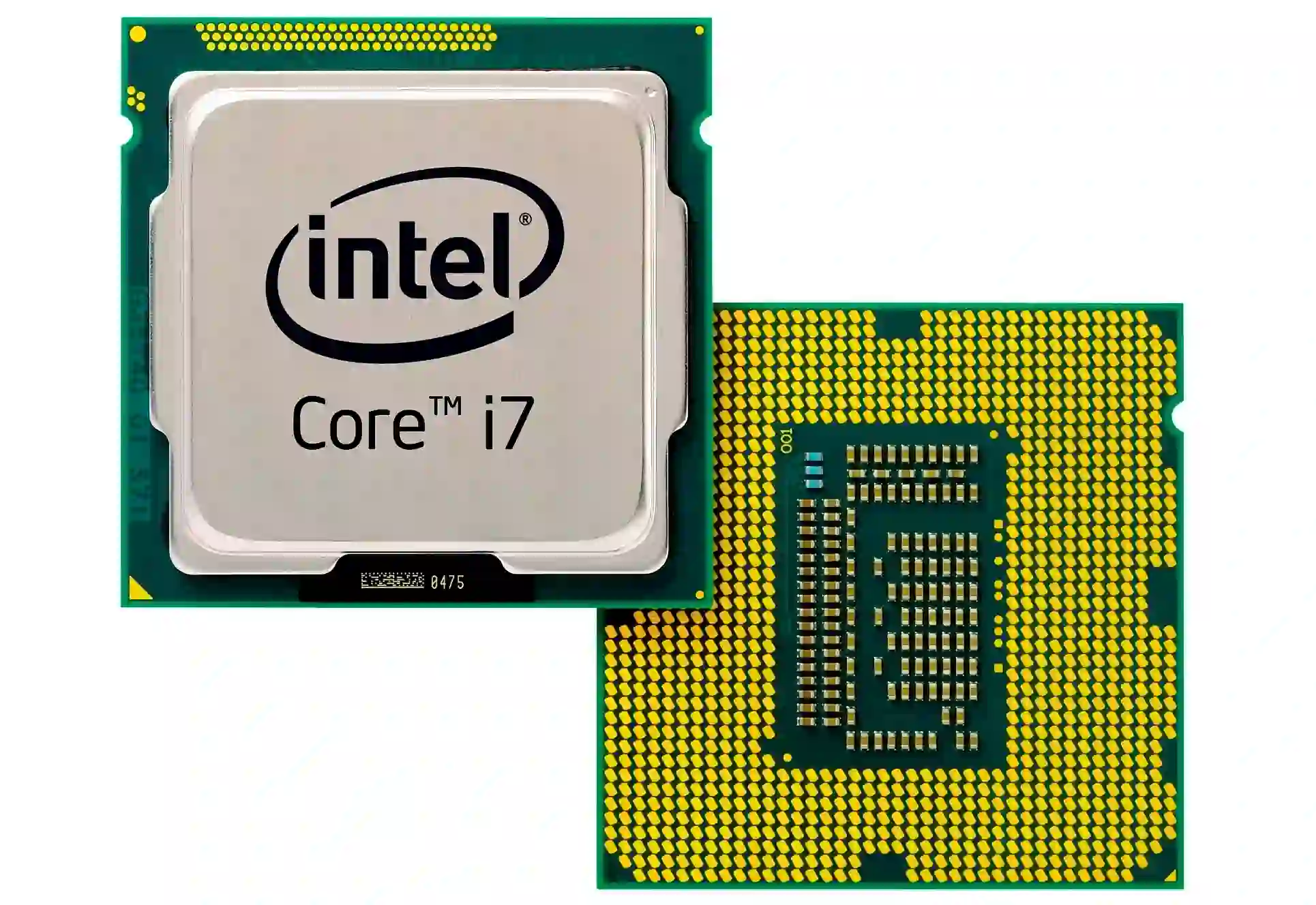
As an electrical engineer, you know that microprocessor PCBs are the heart of countless electronic devices, from industrial controllers to consumer gadgets. When these boards fail, it can lead to costly downtime or product failures. Effective troubleshooting not only saves time and money but also ensures the reliability of your designs. In this guide, we’ll break down the process into manageable steps, helping you pinpoint issues and apply fixes with confidence.
Understanding Common PCB Problems in Microprocessor Boards
Before diving into troubleshooting techniques, let’s explore some common PCB problems specific to microprocessor boards. Recognizing these issues early can save hours of guesswork.
- Power Supply Failures: Microprocessors require stable voltage levels, often between 1.2V and 3.3V, depending on the chip. A deviation as small as 0.1V can cause erratic behavior or complete failure.
- Signal Integrity Issues: High-speed signals in microprocessor circuits can suffer from crosstalk or impedance mismatches if traces aren’t designed with proper widths or spacing. For instance, a 50-ohm impedance mismatch can degrade signal quality at frequencies above 100 MHz.
- Component Failures: Capacitors, resistors, or the microprocessor itself can fail due to overheating, manufacturing defects, or aging. Surface-mount capacitors, for example, are notorious for shorting out over time, as noted in discussions on platforms like X.
- Thermal Stress: Microprocessors generate significant heat, and poor thermal management can lead to solder joint cracks or component burnout.
- Software-Hardware Mismatch: Sometimes, the issue isn’t hardware-related but stems from firmware or software bugs affecting how the microprocessor operates.
By keeping these issues in mind, you can narrow down the root cause of a malfunction during PCB failure analysis.
Step-by-Step Guide to Microprocessor PCB Troubleshooting
Let’s walk through a systematic process for diagnosing microprocessor issues. This method ensures you cover all bases without wasting time on unnecessary tests.
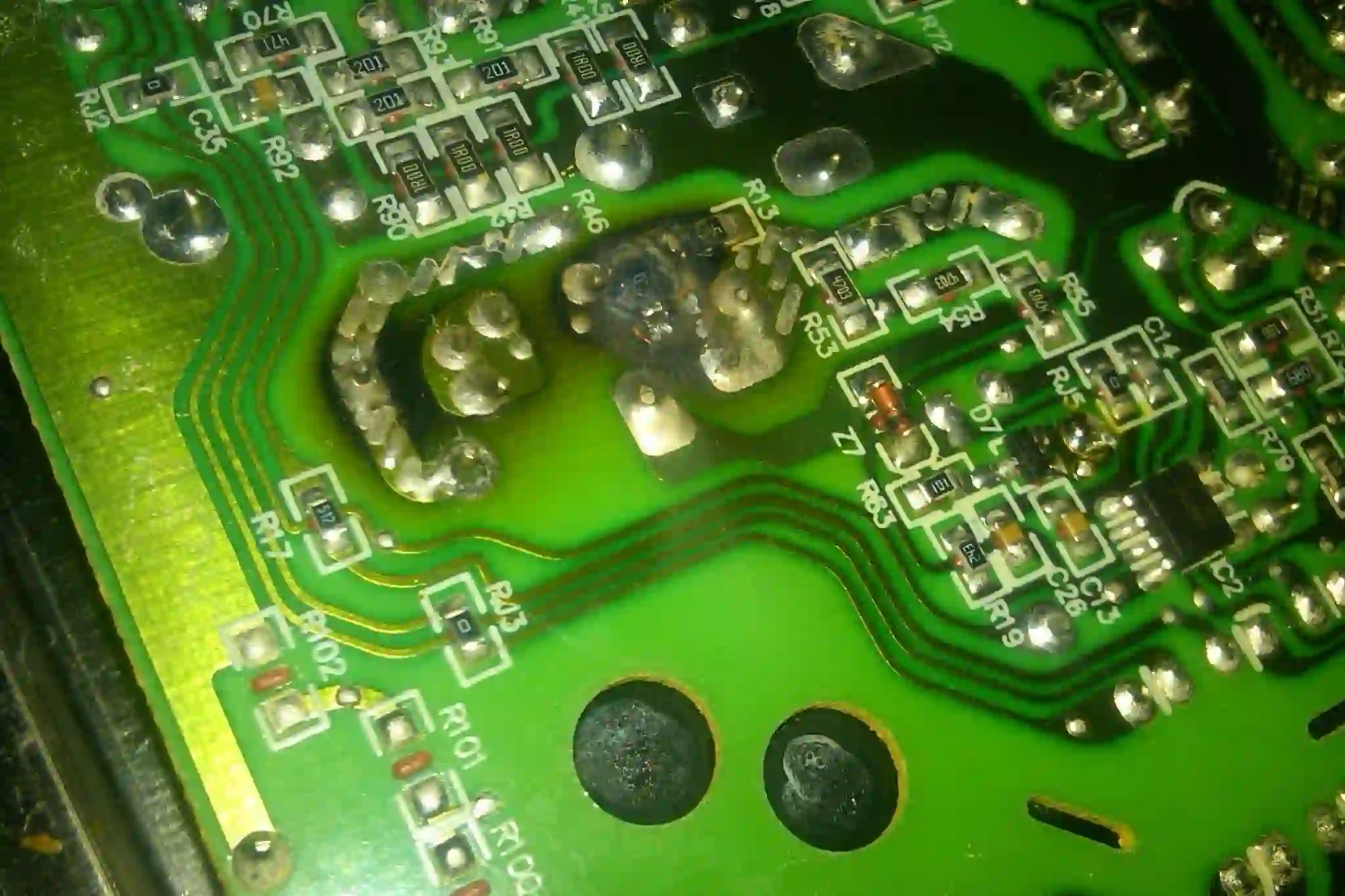
Step 1: Visual Inspection
Start with a thorough visual check of the PCB. Look for obvious signs of damage, such as:
- Burnt components or blackened areas on the board.
- Cracked or bulging capacitors, which often indicate failure.
- Broken traces or solder joints, especially near high-heat areas like the microprocessor.
Use a magnifying glass or a microscope for surface-mount components, as defects can be tiny. A visual inspection can quickly reveal issues that don’t require advanced tools.
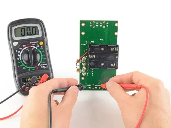
Step 2: Power Supply Testing
Since power issues are a leading cause of microprocessor failures, verify the supply voltages next. Use a multimeter to check the input voltage and the regulated outputs feeding the microprocessor. For example, if your microprocessor requires 1.8V for its core, ensure the voltage at the pin is within ±5% of this value (1.71V to 1.89V).
Also, inspect the power delivery network for ripple or noise using an oscilloscope. Excessive ripple—say, above 50mV peak-to-peak—can cause the microprocessor to reset or behave unpredictably.
Step 3: Signal Integrity Analysis
Signal integrity is critical for microprocessor PCBs, especially with high-speed data lines. Use an oscilloscope to check clock signals and data buses for overshoot, undershoot, or timing errors. For instance, a clock signal operating at 25 MHz should have clean edges with rise times under 1 ns to avoid jitter.
If you suspect crosstalk, examine the PCB layout. Are high-speed traces routed too close to each other? Are there adequate ground planes? A spacing of at least 3x the trace width can minimize interference in many designs.
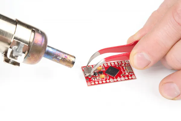
Step 4: Component Testing
If power and signals check out, test individual components. Start with passive components like capacitors and resistors using a multimeter or LCR meter. A shorted capacitor near the microprocessor’s power pins, for instance, can pull down the voltage and halt operation.
For the microprocessor itself, check for signs of life by verifying clock activity or reset signals. If the chip is dead, it might need replacement—a task requiring precision soldering skills.
Step 5: Thermal and Environmental Checks
Overheating is a silent killer of microprocessor PCBs. Use a thermal camera to identify hot spots on the board. If the microprocessor or nearby voltage regulators exceed safe operating temperatures (often 85°C to 105°C, depending on the datasheet), improve cooling with heat sinks or better airflow.
Also, consider environmental factors like humidity or dust, which can cause corrosion or short circuits over time.
Step 6: Firmware and Software Validation
If hardware tests don’t reveal the issue, the problem might lie in the firmware. Reload the firmware or test with a known good version. Use debugging tools like JTAG or SWD interfaces to step through the code and check if the microprocessor executes instructions as expected.
Advanced PCB Repair Techniques for Microprocessor Boards
Once you’ve identified the issue through microprocessor PCB troubleshooting, it’s time to apply PCB repair techniques. Here are some practical methods tailored for engineers:
Replacing Faulty Components
For surface-mount components like capacitors or resistors, use a hot air rework station to desolder and replace them. Ensure the replacement part matches the original specifications—mismatching a 10uF capacitor with a 1uF one can destabilize the power supply.
Replacing a microprocessor is trickier due to fine-pitch pins or BGA (Ball Grid Array) packaging. For BGA chips, you’ll need a specialized rework station with precise temperature control to avoid damaging nearby components.
Repairing Traces and Solder Joints
Broken traces can often be fixed with conductive epoxy or by soldering a small jumper wire. For cracked solder joints, reflow the joint with a soldering iron and fresh solder. Be cautious—excessive heat (above 300°C for more than 10 seconds) can damage the PCB or components.
Addressing Signal Integrity with Layout Fixes
If signal integrity issues stem from poor layout, temporary fixes like adding termination resistors (e.g., 50 ohms for high-speed lines) can help. For permanent solutions, redesign the PCB with better trace routing and ground planes in mind.
Preventing Future Microprocessor PCB Failures
Troubleshooting and repair are essential, but prevention is even better. Here are tips to minimize common PCB problems in future designs:
- Design for Thermal Management: Include adequate heat sinks and ventilation in your design. Place thermal vias under high-power components to dissipate heat.
- Use High-Quality Components: Opt for reliable brands and check datasheets for temperature and voltage ratings that match your application.
- Follow Signal Integrity Guidelines: Maintain consistent impedance for high-speed traces (e.g., 50 ohms) and avoid sharp corners in routing.
- Test Early and Often: Prototype and stress-test your PCB under real-world conditions to catch issues before mass production.
Tools Every Engineer Needs for PCB Troubleshooting
Having the right tools makes diagnosing microprocessor issues much easier. Here’s a list of must-haves:
- Multimeter: For measuring voltage, current, and continuity.
- Oscilloscope: Essential for analyzing signal waveforms and timing.
- Thermal Camera: To detect overheating components.
- Hot Air Rework Station: For desoldering and replacing components.
- Magnifying Tools: Such as a loupe or microscope for inspecting tiny components.
- Logic Analyzer: Useful for debugging digital signals in microprocessor circuits.
Case Study: Diagnosing a Real-World Microprocessor Issue
Let me share a real-world example to illustrate these concepts. A few years ago, I worked on a project involving an embedded system with an ARM Cortex-M4 microprocessor. The board powered on but failed to execute the firmware. After a visual inspection showed no obvious damage, I checked the power supply and found the core voltage was only 1.1V instead of the required 1.2V—a 0.1V shortfall causing the issue.
Using a multimeter, I traced the problem to a shorted decoupling capacitor near the microprocessor. After replacing the 10uF capacitor with a new one, the voltage stabilized, and the board functioned perfectly. This experience reinforced the importance of starting with power checks during PCB failure analysis.
Conclusion: Mastering Microprocessor PCB Troubleshooting
Troubleshooting microprocessor PCBs doesn’t have to be overwhelming. By following a structured approach—visual inspection, power testing, signal analysis, component checks, and repair—you can tackle even the toughest issues. Whether you’re dealing with common PCB problems or complex microprocessor issues, the techniques in this guide will help you diagnose and fix problems efficiently.


