 ALLPCB


Are you struggling to choose the perfect connectors for your printed circuit board (PCB) components? Whether you’re designing for signal integrity, high-current applications, or harsh environments, selecting the right PCB connector is critical to your project’s success. In this comprehensive guide, we’ll walk you through everything you need to know about PCB connector types, how to ensure signal integrity, and the best options for high-current or waterproof needs. We’ll also cover mounting techniques to help you make informed decisions for your designs.
As an electrical engineer, you know that a single wrong choice in connectors can lead to signal loss, power failures, or even complete system breakdowns. That’s why we’ve crafted this ultimate guide to address your specific needs and challenges. Let’s dive into the world of PCB connectors and help you find the perfect match for your next project.
Why Choosing the Right PCB Connector Matters
PCB connectors are the backbone of any electronic system, ensuring reliable communication and power delivery between components. A poorly chosen connector can result in signal degradation, overheating, or mechanical failure. For instance, using a connector not rated for high-current applications in a power supply circuit could cause thermal runaway, damaging your PCB and components. On the other hand, selecting a connector optimized for your specific needs can improve performance, reduce costs, and extend the lifespan of your design.
In this guide, we’ll break down the key factors to consider when selecting connectors, including a PCB connector types comparison, tips for selecting PCB connectors for signal integrity, and solutions for high-current PCB connectors and waterproof PCB connectors. We’ll also explore PCB connector mounting techniques to ensure a secure and lasting connection.
Understanding PCB Connector Types: A Detailed Comparison
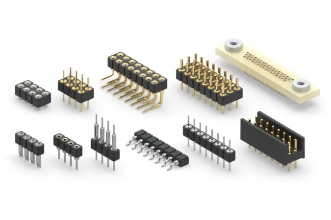
Before selecting a connector, it’s essential to understand the different types available and their specific applications. Here’s a PCB connector types comparison to help you navigate your options:
1. Board-to-Board Connectors
These connectors link two PCBs together, often in compact designs where space is limited. They are ideal for multi-board systems in devices like smartphones or industrial controllers. Board-to-board connectors come in various configurations, including mezzanine (stacked) and coplanar (side-by-side) setups, with pitch sizes as small as 0.4 mm for high-density applications.
2. Wire-to-Board Connectors
Wire-to-board connectors are used to connect external wires or cables to a PCB. They’re commonly found in power supplies and sensor applications. These connectors often feature locking mechanisms to prevent accidental disconnection and can handle currents ranging from 1A to 20A, depending on the design.
3. Board-to-Wire Connectors
Similar to wire-to-board, these connectors allow wires to interface with a PCB but are often designed for quick assembly and disassembly. They’re popular in automotive and consumer electronics, where modular designs are key.
4. Edge Connectors
Edge connectors are used to connect a PCB to a larger system, often seen in computer expansion cards like PCIe slots. They offer high reliability and can support high-speed data transfer rates, sometimes exceeding 32 Gbps in modern designs.
5. Backplane Connectors
Backplane connectors are designed for high-speed, high-density applications in servers and telecommunications equipment. They can handle multiple signals simultaneously and are built to minimize crosstalk and signal loss, often supporting data rates up to 56 Gbps.
Each type of connector serves a unique purpose, so understanding your project’s requirements—such as space constraints, signal speed, or environmental factors—is crucial. For instance, if you’re working on a compact IoT device, a fine-pitch board-to-board connector might be your best bet.
Selecting PCB Connectors for Signal Integrity
Signal integrity is a top priority in high-speed and sensitive electronic designs. Poor signal integrity can lead to data errors, noise, or complete system failure. When selecting PCB connectors for signal integrity, consider the following factors:
Impedance Matching
Connectors should match the impedance of the PCB traces to prevent reflections. For high-speed signals, look for connectors with controlled impedance, often around 50 ohms for single-ended signals or 100 ohms for differential pairs. Mismatched impedance can cause signal reflections, leading to data corruption.
Low Crosstalk and EMI
Crosstalk occurs when signals from adjacent lines interfere with each other. Choose connectors with shielding or ground pins between signal pins to reduce crosstalk. Additionally, connectors with built-in electromagnetic interference (EMI) protection are essential for applications near RF sources or in noisy environments.
High-Speed Capabilities
For applications like USB 3.0 or PCIe 4.0, select connectors rated for high-speed data transfer. Some modern connectors support speeds up to 56 Gbps while maintaining signal integrity through optimized pin layouts and materials like low-loss dielectrics.
Practical Tip
During a recent project designing a high-speed data acquisition system, I encountered significant signal degradation due to a poorly chosen connector. Switching to a shielded backplane connector with a 50-ohm impedance rating resolved the issue, improving data accuracy by over 30%. Always simulate your design with tools like SPICE or HyperLynx to predict signal behavior before finalizing your connector choice.
High-Current PCB Connectors: Powering Your Designs
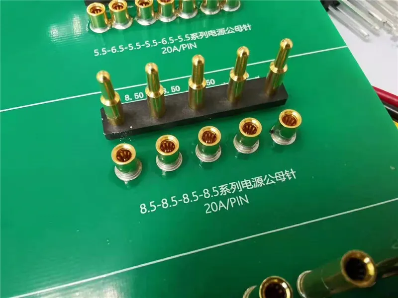
For applications requiring substantial power delivery, such as motor controllers or power supplies, high-current PCB connectors are essential. These connectors are designed to handle currents ranging from 10A to over 100A without overheating or degrading.
Key Features to Look For
- Contact Material: High-current connectors often use copper alloys with gold or silver plating to minimize resistance and heat buildup.
- Thermal Management: Look for connectors with large contact areas and heat dissipation features to prevent thermal runaway. Some connectors can handle up to 125°C operating temperatures.
- Current Rating: Ensure the connector’s current rating exceeds your application’s peak load by at least 20% to account for surges. For example, a 50A-rated connector is suitable for a continuous 40A load.
Application Example
In industrial automation systems, high-current connectors are often used to power servo motors. A poorly rated connector can lead to voltage drops, causing motor stalls. I’ve seen designs fail because a 20A connector was used for a 25A peak load—always overspecify for safety.
Waterproof PCB Connectors: Protecting Against the Elements
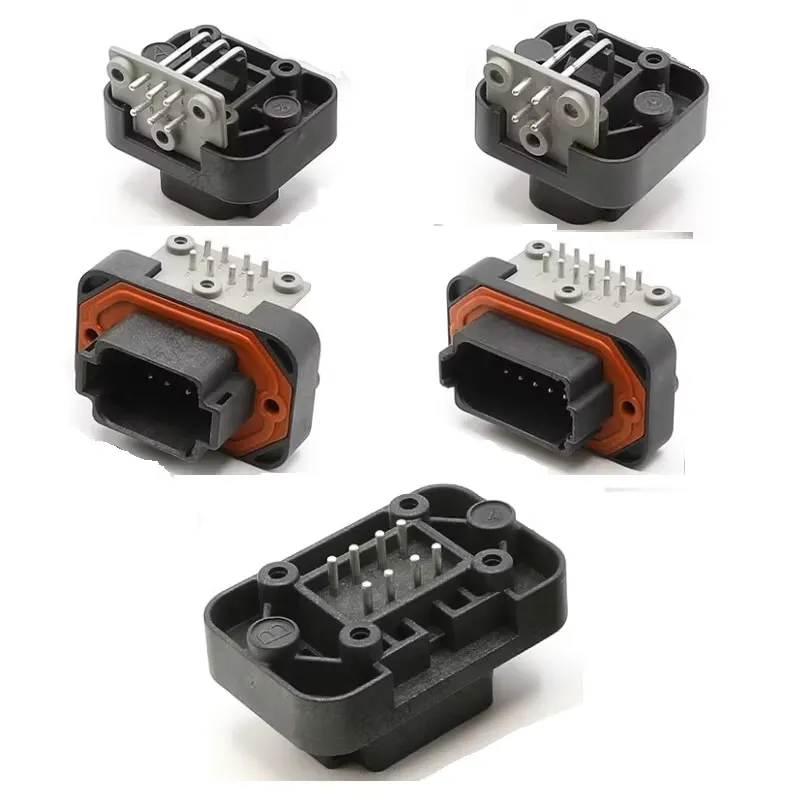
For outdoor or harsh environment applications, waterproof PCB connectors are a must. These connectors prevent moisture ingress, which can cause short circuits or corrosion. They’re widely used in automotive, marine, and industrial equipment.
IP Ratings Explained
Waterproof connectors are rated by their Ingress Protection (IP) level. An IP67 rating means the connector is dust-tight and can withstand immersion in water up to 1 meter for 30 minutes. For more extreme conditions, look for IP68 or IP69K ratings, which offer higher protection against prolonged submersion or high-pressure water jets.
Sealing Mechanisms
Most waterproof connectors feature rubber gaskets or O-rings to seal the connection. Some also include locking mechanisms to ensure a tight fit. For example, certain USB-C PCB connector now offer IPX8 ratings, making them suitable for rugged handheld devices.
Real-World Use Case
While working on a marine sensor project, I opted for an IP68-rated wire-to-board connector to protect against saltwater exposure. Despite months of testing in harsh conditions, the connector showed no signs of corrosion, ensuring reliable data transmission. Always check the material specifications—some connectors use stainless steel or specialized coatings for added durability.
PCB Connector Mounting Techniques: Ensuring a Secure Fit
The way a connector is mounted to a PCB significantly impacts its reliability and ease of assembly. Let’s explore common PCB connector mounting techniques to help you choose the best method for your design.
Through-Hole Mounting
Through-hole connectors have pins that pass through the PCB and are soldered on the opposite side. This method offers excellent mechanical strength, making it ideal for high-vibration environments like automotive systems. However, it’s less suited for high-density designs due to the larger footprint.
Surface-Mount Technology (SMT)
SMT connectors are soldered directly onto the PCB surface, saving space and enabling high-density layouts. They’re common in consumer electronics but require precise placement during assembly to avoid misalignment. SMT connectors often support reflow soldering, streamlining mass production.
Press-Fit Mounting
Press-fit connectors use pins that are pressed into plated-through holes without soldering. This technique is ideal for applications requiring frequent connector replacement or where soldering heat could damage components. Press-fit designs can withstand up to 100 mating cycles without degrading.
Hybrid Mounting
Some connectors combine through-hole and SMT features for added stability. For instance, a connector might use PCBA SMT for signal pins and through-hole for power pins to balance space efficiency with mechanical strength.
Key Considerations When Selecting PCB Connectors
Beyond the specific categories above, here are some general factors to keep in mind when choosing connectors for your PCB components:
- Environmental Conditions: Consider temperature, humidity, and exposure to chemicals. For high-temperature environments, choose connectors rated for up to 125°C or higher.
- Mating Cycles: How often will the connector be plugged and unplugged? Some connectors are rated for only 50 cycles, while others can handle over 10,000.
- Cost vs. Performance: High-end connectors with advanced features (e.g., shielding, high-speed support) are more expensive. Balance your budget with performance needs.
- Manufacturer Support: Opt for connectors from reputable manufacturers who provide detailed datasheets and simulation models. This can save hours of troubleshooting during design.
Conclusion: Making the Right Choice for Your PCB Design
Selecting the right connectors for your PCB components doesn’t have to be a daunting task. By understanding the different PCB connector types, prioritizing signal integrity, and considering specific needs like high-current or waterproof capabilities, you can ensure a reliable and efficient design. Additionally, choosing the appropriate mounting technique will enhance the durability and performance of your system.
As an electrical engineer, your goal is to create designs that are both innovative and dependable. Use this guide as a roadmap to navigate the complex world of PCB connectors. Whether you’re working on a high-speed data system or a rugged outdoor application, the right connector can make all the difference.


