ALLPCB


If you're looking to understand rigid PCB assembly techniques, particularly Surface Mount Technology (SMT) and Through-Hole Technology (THT), you've come to the right place. At ALLPCB, we know that choosing the right assembly method is critical for the performance, durability, and cost of your electronic projects. In this comprehensive guide, we'll dive deep into rigid PCB SMT assembly and rigid PCB through-hole assembly, exploring their processes, benefits, and best practices for rigid PCB soldering techniques and rigid PCB component placement. Whether you're designing a compact consumer device or a robust industrial system, this blog will help you make informed decisions.
Introduction to Rigid PCB Assembly
Rigid PCBs are the foundation of most electronic devices, offering a sturdy base for mounting components in everything from smartphones to industrial machinery. Assembling these boards requires precision and an understanding of different techniques to ensure reliability and efficiency. The two primary methods used today are Surface Mount Technology (SMT) and Through-Hole Technology (THT). Each has unique strengths, making them suitable for different applications. In the sections below, we'll break down these methods, focusing on how they apply to rigid PCB assembly and providing practical insights for engineers and designers.
What is Rigid PCB SMT Assembly?
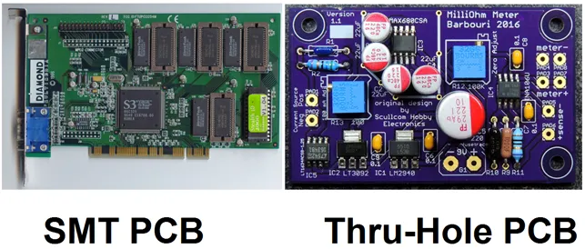
Rigid PCB SMT assembly refers to the process of mounting electronic components directly onto the surface of a printed circuit board. This technique is widely used in modern electronics due to its ability to support smaller, lighter, and more densely packed designs. SMT components, such as resistors, capacitors, and integrated circuits, have small metal tabs or leads that are soldered directly to pads on the PCB surface, eliminating the need for drilled holes.
Key Steps in SMT Assembly
The SMT assembly process is highly automated, making it efficient for mass production. Here's a detailed look at the steps involved:
- Solder Paste Application: A stencil is used to apply solder paste—a mixture of tiny solder particles and flux—onto specific areas of the PCB where components will be placed. Precision is key to avoid excess paste, which can cause short circuits.
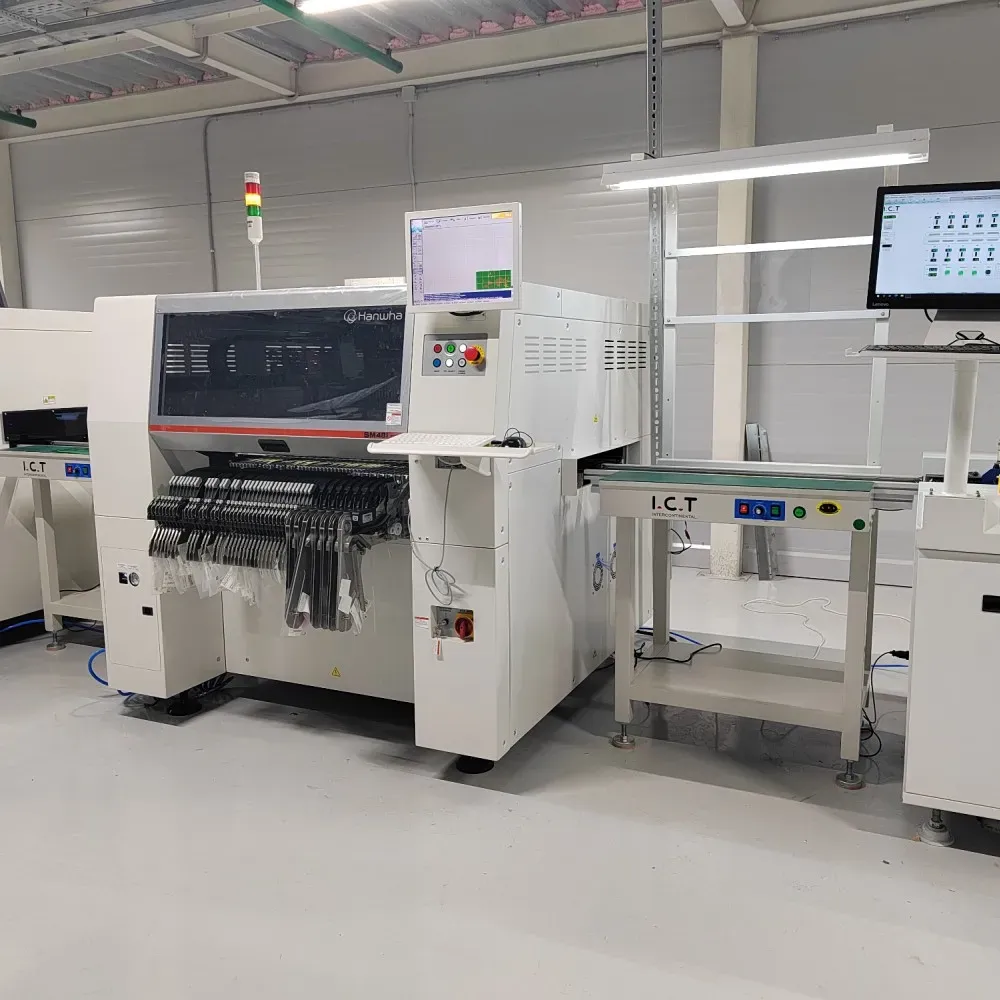
- Component Placement: Automated pick-and-place machines position SMT components onto the solder paste with high accuracy, often at speeds of thousands of components per hour.
- Reflow Soldering: The PCB passes through a reflow oven, where controlled heat melts the solder paste, creating a permanent bond between the components and the board. Temperatures typically reach 240-260°C, depending on the solder type (e.g., lead-free solder requires higher temperatures).
- Inspection: Automated Optical Inspection (AOI) systems check for placement errors, solder defects, or missing components to ensure quality.
Advantages of SMT for Rigid PCB Assembly
SMT offers several benefits that make it the preferred choice for many modern applications:
- Compact Design: SMT components are much smaller than through-hole parts, allowing for higher component density and reduced board size—crucial for portable devices.
- Cost-Effective Production: Automation reduces labor costs and increases production speed, making SMT ideal for large-scale manufacturing.
- Better High-Frequency Performance: With shorter lead lengths, SMT components exhibit lower parasitic inductance and capacitance, improving signal integrity at high frequencies (e.g., above 100 MHz).
Challenges in SMT Assembly
While SMT is highly efficient, it comes with challenges. The small size of components can make manual rework difficult, and thermal stress during reflow soldering can sometimes damage sensitive parts if not carefully managed. Additionally, SMT is less suited for high-power or high-stress applications where mechanical strength is critical.
What is Rigid PCB Through-Hole Assembly?
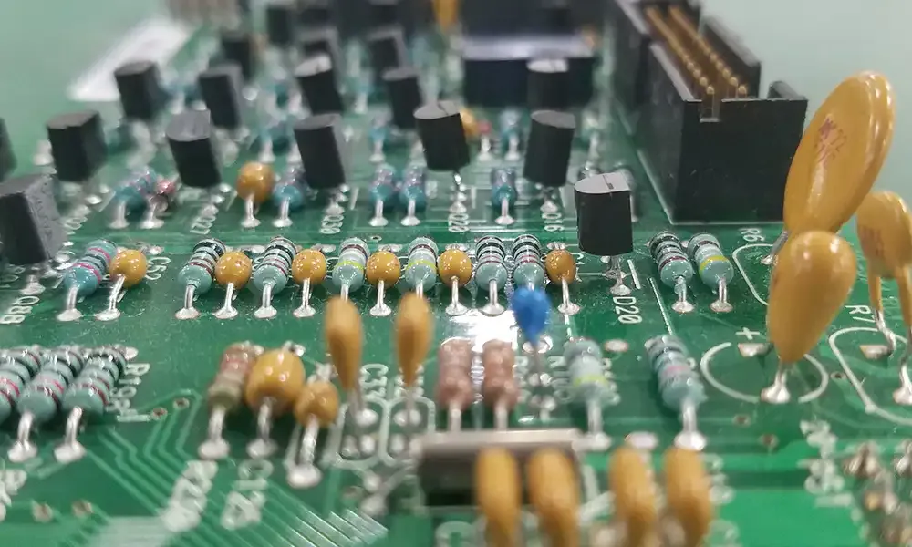
Rigid PCB through-hole assembly is a traditional method where component leads are inserted through drilled holes in the PCB and soldered on the opposite side. This technique is known for its durability and is often used in applications where components must withstand mechanical stress or high power loads, such as in automotive or industrial electronics.
Key Steps in Through-Hole Assembly
Through-hole assembly is less automated than SMT and often involves manual steps, especially for low-volume production. Here's how it works:
- Component Insertion: Components with long leads, such as resistors, capacitors, or connectors, are inserted into pre-drilled holes on the PCB. This can be done manually or with semi-automated insertion machines.
- Soldering: Once components are in place, soldering is performed either manually with a soldering iron or through wave soldering, where the board passes over a wave of molten solder (typically at 250-270°C) to bond the leads to the pads.
- Trimming and Cleaning: Excess lead length is trimmed, and the board is cleaned to remove flux residue, ensuring reliability and preventing corrosion.
- Inspection: Visual inspection or testing ensures that all components are securely soldered and functioning as expected.
Advantages of Through-Hole for Rigid PCB Assembly
Through-hole technology remains relevant due to its unique strengths:
- Mechanical Strength: The leads passing through the board and soldered on both sides provide a robust connection, ideal for components under physical stress or vibration.
- High Power Handling: Through-hole components can handle higher currents and voltages, making them suitable for power supplies or industrial equipment.
- Ease of Repair: Larger components and accessible leads make through-hole boards easier to repair or modify, especially in prototyping or low-volume production.
Challenges in Through-Hole Assembly
Through-hole assembly has limitations in modern, compact designs. It requires more board space due to the need for drilled holes and larger components, and the process is slower and less cost-effective for high-volume production compared to SMT. Additionally, drilling holes increases manufacturing costs and can weaken the board if not done carefully.
Comparing SMT and Through-Hole for Rigid PCB Assembly
Choosing between rigid PCB SMT assembly and rigid PCB through-hole assembly depends on your project's specific needs. Here's a detailed comparison to help you decide:
- Size and Density: SMT allows for smaller, denser designs, often reducing board size by up to 50% compared to through-hole. If space is a constraint, SMT is the better choice.
- Durability: Through-hole provides stronger mechanical bonds, making it ideal for applications where the PCB may experience vibration or shock (e.g., automotive systems).
- Production Speed: SMT's automated processes can achieve placement rates of 20,000-50,000 components per hour, while through-hole often requires manual labor, slowing down production.
- Cost: SMT is generally more cost-effective for large runs due to automation, while through-hole may be cheaper for small batches or prototypes due to lower setup costs.
- Signal Performance: SMT components, with their shorter leads, offer better performance at high frequencies, reducing signal loss in applications like RF circuits operating at 2.4 GHz or higher.
In many cases, a hybrid approach combining both SMT and through-hole components on the same rigid PCB is used. For example, SMT can be used for smaller, high-density components, while through-hole is reserved for connectors or high-power parts that require extra strength.
Rigid PCB Soldering Techniques for SMT and Through-Hole
Rigid PCB soldering techniques are critical to ensuring reliable connections and preventing failures. Here's how soldering differs between SMT and through-hole assembly, along with best practices:
Soldering in SMT Assembly
SMT soldering relies on reflow soldering, where solder paste is heated to form a bond. Key considerations include:
- Temperature Profiles: A precise reflow profile with preheating (150-180°C), soaking, and peak temperatures (240-260°C) prevents thermal shock to components.
- Solder Paste Quality: Using high-quality lead-free or leaded solder paste ensures consistent melting and adhesion. Poor paste can lead to defects like tombstoning, where components lift off one side.
- Stencil Design: Stencil thickness (typically 0.1-0.15 mm) and aperture size must match component pads to avoid excess or insufficient paste.
Soldering in Through-Hole Assembly
Through-hole soldering can be done via wave soldering or manual soldering. Best practices include:
- Wave Soldering Parameters: Control solder temperature (250-270°C) and wave height to ensure even coverage without damaging the board.
- Flux Application: Flux cleans the surfaces and improves solder flow. Water-soluble or no-clean flux is often used to minimize residue.
- Manual Soldering Tips: Use a soldering iron with a temperature of 300-350°C for quick, clean joints. Avoid prolonged heat to prevent damage to the PCB or components.
Rigid PCB Component Placement Strategies
Rigid PCB component placement is a critical step that affects assembly efficiency, performance, and reliability. Here are strategies for both SMT and through-hole components:
Component Placement for SMT
- Alignment with Pads: Ensure components are precisely aligned with solder pads to avoid issues like misalignment or insufficient solder joints. Automated pick-and-place machines achieve placement accuracy within 0.01 mm.
- Spacing: Maintain adequate spacing between components to prevent thermal interference during reflow soldering. A minimum gap of 0.2-0.3 mm is often recommended for small components.
- Orientation: Orient components like diodes or ICs consistently to simplify inspection and reduce assembly errors.
Component Placement for Through-Hole
- Hole Alignment: Ensure leads fit snugly into drilled holes without excessive force, which can damage the component or board. Hole diameters are typically 0.2-0.3 mm larger than the lead diameter.
- Component Height: Position components at a uniform height above the board to facilitate wave soldering and ensure even solder flow.
- Stress Points: Place larger, heavier components in areas of the board that can handle mechanical stress, often near mounting points or edges.
Effective component placement also involves considering the overall design for manufacturability (DFM). For instance, grouping similar components together can streamline assembly, while placing heat-sensitive parts away from high-heat areas improves reliability.
Best Practices for Rigid PCB Assembly
To achieve optimal results in rigid PCB assembly, follow these best practices tailored for both SMT and through-hole techniques:
- Design with Assembly in Mind: Use design software to simulate component placement and soldering processes, identifying potential issues before manufacturing begins.
- Choose the Right Materials: Select PCB substrates (e.g., FR-4) and solder types that match your application's thermal and mechanical requirements. For high-frequency designs, consider materials with low dielectric constants (e.g., 2.2-3.5).
- Quality Control: Implement rigorous inspection processes, such as AOI for SMT and visual checks for through-hole, to catch defects early.
- Thermal Management: Account for heat dissipation in your design, especially for high-power through-hole components or densely packed SMT boards, to prevent overheating (e.g., junction temperatures exceeding 125°C).
Conclusion
Understanding rigid PCB SMT assembly and rigid PCB through-hole assembly is essential for creating reliable and efficient electronic products. SMT excels in compact, high-speed production with excellent signal performance, while through-hole offers unmatched durability for demanding applications. By mastering rigid PCB soldering techniques and rigid PCB component placement, you can optimize your designs for both performance and manufacturability. At ALLPCB, we're committed to supporting your projects with high-quality assembly services tailored to your needs. Whether you're working on a small prototype or a large production run, leveraging the right assembly technique will ensure your rigid PCBs meet the highest standards.