 ALLPCB


If you're an electrical engineer looking to master the art of reworking fine-pitch components, you've come to the right place. Fine pitch rework, component alignment, microscopic rework, precision soldering, and high-density rework are critical skills in modern electronics assembly. This blog will guide you through the essentials of achieving precision and accuracy when handling these tiny, densely packed components. Whether you're dealing with surface-mount devices (SMDs) with pitches as small as 0.3mm or tackling complex ball grid arrays (BGAs), we'll cover proven techniques, tools, and tips to ensure success.
In the detailed sections below, we'll dive into the challenges of fine pitch rework, explore best practices for component alignment, and share actionable advice on precision soldering for high-density assemblies. Let's get started on building your expertise in this demanding yet rewarding field.
What Are Fine-Pitch Components and Why Are They Challenging?
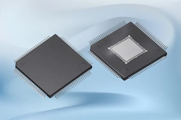
Fine-pitch components are electronic parts with closely spaced leads or pins, often with pitches (the distance between pins) of 1mm or less, sometimes down to 0.3mm. These include SMDs like quad flat no-leads (QFNs), chip-scale packages (CSPs), and BGAs with hundreds or thousands of connections. They are essential for creating compact, high-performance printed circuit boards (PCBs) used in smartphones, medical devices, and automotive electronics.
The challenge with fine pitch rework lies in their small size and tight spacing. A slight misalignment during soldering can cause short circuits or open connections, leading to device failure. Additionally, inspecting solder joints under such high-density conditions often requires specialized microscopic tools. Overheating during rework can also damage delicate components or the PCB substrate, making precision and control non-negotiable.
Essential Tools for Fine Pitch Rework and Precision Soldering
Before diving into techniques, let's talk about the tools you need for successful fine pitch rework and high-density assembly. Having the right equipment can make or break your project.
- Hot Air Rework Station: A must-have for removing and replacing fine-pitch components. Look for stations with adjustable temperature (up to 450°C) and airflow control to avoid damaging nearby parts.
- Soldering Iron with Fine Tips: Use a soldering iron with a tip size of 0.2mm to 0.5mm for precision soldering. Temperature control between 250°C and 350°C is crucial to prevent overheating.
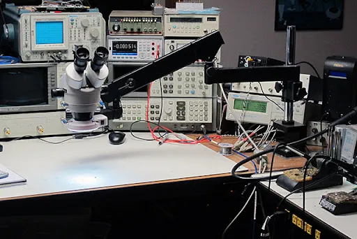
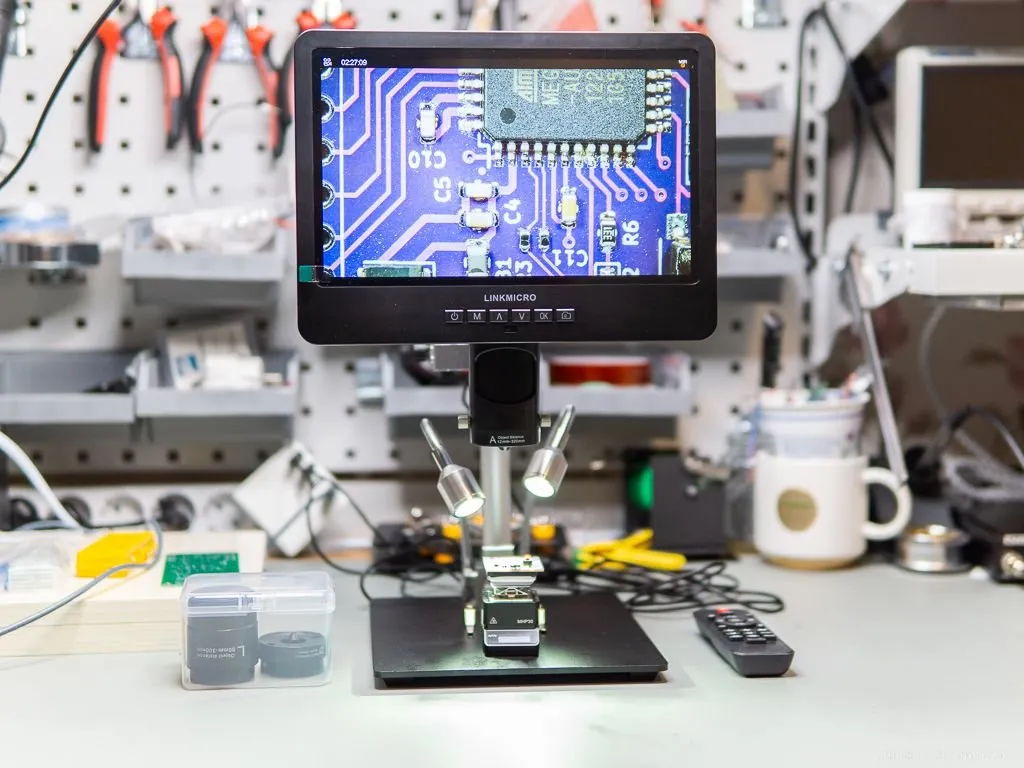
- Stereo Microscope or Digital Microscope: Microscopic rework demands visibility. A microscope with 10x to 40x magnification helps with component alignment and solder joint inspection.
- Solder Paste and Flux: Choose a high-quality solder paste with fine particles (Type 4 or 5) for pitches below 0.5mm. Flux ensures clean joints and prevents bridging.
- Precision Tweezers: Anti-static tweezers with fine tips are essential for handling tiny components without damaging them.
- Stencil and Fixture Plates: Custom stencils for solder paste application and fixture plates for alignment ensure consistency in high-density rework.
Investing in quality tools tailored for fine pitch work will save you time and reduce errors. For instance, a hot air station with a precise nozzle can target a 0.4mm pitch QFN without affecting adjacent components.
Step-by-Step Guide to Fine Pitch Rework
Reworking fine-pitch components requires a systematic approach to avoid costly mistakes. Below is a detailed process to help you achieve precision in every step.
1. Preparation and Inspection
Start by inspecting the PCB and component under a microscope to identify issues like solder bridges, misaligned pins, or damaged pads. Ensure your workspace is clean and static-free to prevent contamination or electrostatic discharge (ESD). Gather all tools and materials, including the correct solder paste and replacement component if needed.
2. Component Removal
Use a hot air rework station to remove the defective component. Set the temperature to around 300°C-350°C (adjust based on the component datasheet) and use a small nozzle to focus heat on the target area. Apply heat evenly for 30-60 seconds until the solder melts, then gently lift the component with tweezers. Avoid excessive heat, as it can lift PCB pads or damage nearby parts.
3. Cleaning the PCB
After removal, clean the PCB pads using a soldering iron and desoldering wick to remove excess solder. Apply flux to the area and wipe it with isopropyl alcohol and a brush to ensure a clean surface for reattachment. Inspect under a microscope to confirm no solder residue or damage remains.
4. Component Alignment for High-Density Rework
Proper component alignment is critical in fine pitch rework. Place the new component using precision tweezers, aligning it with the PCB pads. For components with no visible pins (like BGAs), consider using alignment markers or copper rectangles on the PCB corners, a technique often shared by engineers on platforms like X for manual assembly. If available, use a fixture plate to hold the component in place. Double-check alignment under a microscope before soldering.
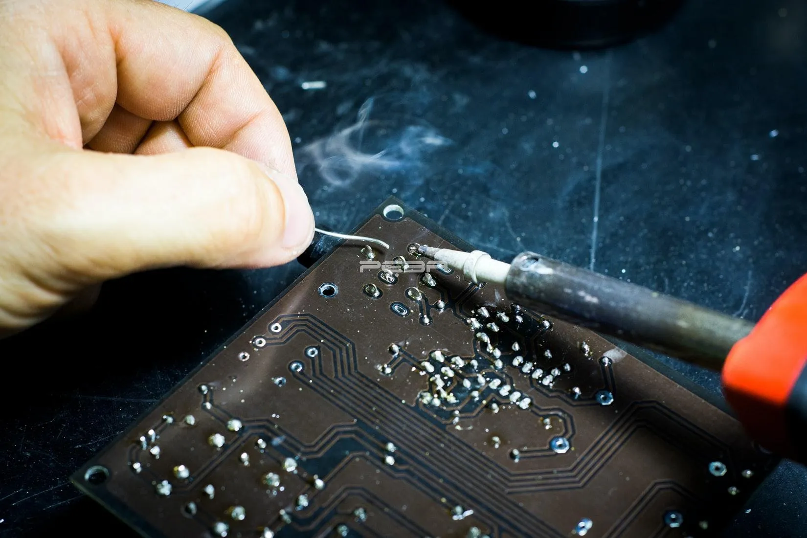
5. Precision Soldering
Apply solder paste using a stencil designed for the specific pitch (e.g., 0.4mm). Ensure the paste volume matches the pad size—too much can cause bridging, while too little can result in weak joints. Use a hot air station or reflow oven to heat the area to the solder’s melting point (typically 220°C-250°C for lead-free solder). For manual soldering, use a fine-tip iron and work on one pin at a time, starting from a corner and moving systematically.
6. Inspection and Testing
Once soldering is complete, inspect the joints under a microscope for bridges, cold solder joints, or misalignment. Use an X-ray inspection system if available for BGAs to check hidden connections. Finally, test the PCB functionality to confirm the rework was successful.
Best Practices for Component Alignment in High-Density Rework
Component alignment is often the most challenging part of high-density rework. Here are some best practices to ensure accuracy:
- Use Visual Aids: Always work under magnification. A stereo microscope with adjustable zoom (10x-40x) helps spot misalignments as small as 0.1mm.
- Alignment Markers: Design PCBs with small alignment markers or copper rectangles at component corners to guide placement, especially for pin-less packages.
- Fixture Plates: Custom fixture plates can hold components in place during soldering, reducing the risk of movement. This is particularly useful for pitches below 0.5mm.
- Practice Patience: Rushing alignment can lead to errors. Take your time to adjust the component until it’s perfectly positioned before applying heat.
One real-world example comes from my experience reworking a 0.4mm pitch QFN for a prototype board. Using a fixture plate and checking alignment under 20x magnification, I reduced placement errors by nearly 80% compared to freehand attempts.
Precision Soldering Tips for Fine Pitch Components
Precision soldering is the heart of fine pitch rework. Here are targeted tips to improve your results:
- Control Temperature: Keep soldering iron or hot air temperatures within the component’s specified range (check datasheets). For most fine-pitch SMDs, 300°C is a safe starting point for hot air, while 260°C works for manual soldering.
- Minimize Solder Paste: Over-applying paste leads to bridges. Use a stencil with apertures sized for the pad (e.g., 0.2mm width for a 0.4mm pitch) to control volume.
- Use Quality Flux: A thin layer of flux improves solder flow and prevents oxidation. As noted in discussions on platforms like X, flux thickness can be critical—apply just enough to be sticky but not visibly thick.
- Work Systematically: Solder corner pins first to anchor the component, then move to remaining pins. This reduces the chance of shifting during the process.
Common Challenges in Fine Pitch Rework and How to Overcome Them
Even with the best tools and5428. Solder Bridges: Use minimal solder paste and inspect joints under magnification. If bridges occur, use desoldering wick with flux to clean them up.
2. Misalignment: Double-check alignment before soldering and use fixtures or markers for accuracy.
3. Overheating: Monitor temperature and limit heat exposure to 30-60 seconds per area to avoid damaging components or lifting pads.
4. Poor Joint Quality: Ensure clean pads and use fresh solder paste for strong, reliable connections.
Addressing these challenges upfront can save hours of troubleshooting later. For instance, during a recent project with a 1,156-pin BGA, careful heat management and flux application (inspired by online engineering communities) made the difference between failure and a perfect reballing job.
Benefits of Mastering Fine Pitch Rework for Engineers
Mastering fine pitch rework and high-density assembly offers several benefits for electrical engineers:
- Cost Savings: Reworking components instead of replacing entire boards reduces project costs.
- Faster Prototyping: Precision rework speeds up iterations during design and testing phases.
- Enhanced Skills: These techniques build your expertise, making you a valuable asset in industries like consumer electronics and aerospace.
- Improved Product Reliability: Accurate rework ensures devices function as intended, reducing field failures.
Conclusion: Elevate Your Fine Pitch Rework Skills
Reworking fine-pitch components is a demanding but essential skill for electrical engineers working on modern, high-density electronics. By focusing on component alignment, precision soldering, and microscopic rework techniques, you can achieve the accuracy needed for success. Invest in the right tools, follow systematic processes, and adopt best practices to tackle even the smallest pitches—down to 0.3mm—with confidence.
Whether you're repairing a smartphone PCB or assembling a cutting-edge medical device, the tips and steps in this guide will help you navigate the challenges of fine pitch rework. Keep practicing, stay patient, and watch your precision improve with every project.


