ALLPCB


Wave soldering is a critical process in PCB assembly, and getting the temperature just right is essential for creating strong, reliable solder joints. If you're searching for the optimal wave soldering temperature profile, the ideal wave soldering temperature range, or how temperature impacts components and lead-free solder, you're in the right place. In short, the typical wave soldering temperature range for lead-free solder is between 250°C and 260°C, while for traditional lead-based solder, it’s around 240°C to 250°C. However, fine-tuning this profile depends on your specific components, board design, and solder type to avoid defects like cold joints or thermal damage.
In this detailed guide, we'll dive deep into everything you need to know about wave soldering temperature effects on components, the best practices for setting the optimal wave soldering temperature for lead-free solder, and actionable tips to improve your soldering results. Whether you're an engineer or a manufacturer, this blog will help you achieve high-quality PCB assemblies with fewer defects.
What is Wave Soldering and Why Does Temperature Matter?
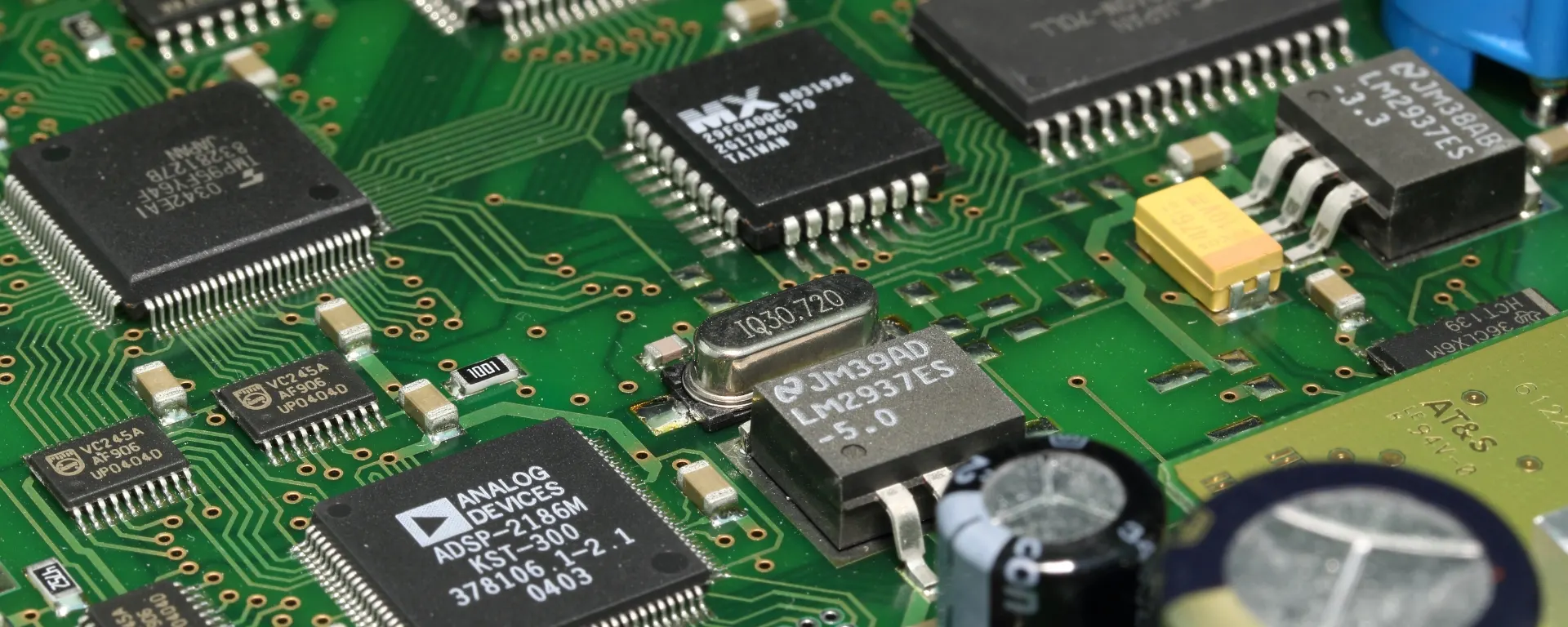
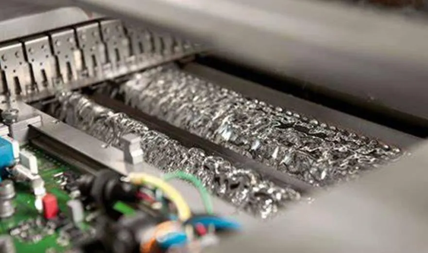
Wave soldering is a bulk soldering method used in electronics manufacturing to attach through-hole components to printed circuit boards (PCBs). During the process, a PCB passes over a wave of molten solder, which bonds the component leads to the board's pads. This technique is fast and efficient, making it ideal for high-volume production.
Temperature plays a starring role in wave soldering. If the solder is too cool, you risk poor wetting and weak joints. If it's too hot, you could damage sensitive components or cause solder bridges. Striking the right balance within the wave soldering temperature range ensures reliable connections and protects the integrity of your PCB.
Understanding the Wave Soldering Temperature Profile
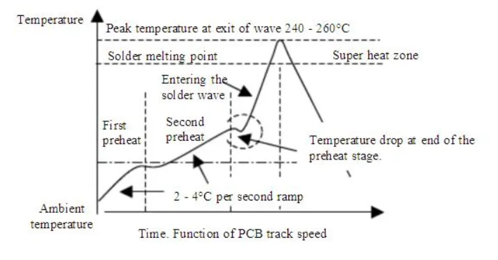
The wave soldering temperature profile refers to the sequence of temperature changes a PCB experiences during the soldering process. This profile typically includes four key stages: preheating, flux activation, soldering, and cooling. Let's break down each stage and its temperature considerations.
1. Preheating Stage
Before the PCB meets the solder wave, it undergoes preheating to gradually raise its temperature. This step, usually set between 100°C and 150°C, reduces thermal shock to components and activates the flux. Preheating typically lasts 60 to 120 seconds, depending on the board size and component density.
2. Flux Activation
Flux is applied to clean the surfaces of the PCB and component leads, ensuring better solder adhesion. During preheating, the flux activates at around 120°C to 150°C, removing oxides and preparing the surfaces for soldering.
Related Reading: Wave Soldering Flux: Selecting the Right Type for Optimal Wetting and Minimal Residue
3. Soldering Stage
This is the heart of the process, where the PCB passes over the molten solder wave. The wave soldering temperature range here is critical. For lead-free solder, the temperature is often set between 250°C and 260°C, while lead-based solder works well at 240°C to 250°C. The contact time with the wave is short—usually 2 to 4 seconds—to prevent overheating.
4. Cooling Stage
After soldering, the PCB cools down to solidify the joints. Rapid cooling can cause thermal stress, so a controlled cooling rate is ideal, often achieved naturally as the board moves away from the wave.
Mastering this wave soldering temperature profile minimizes defects like insufficient wetting, solder bridges, or component damage. Adjusting the profile based on your specific setup is key to consistent results.
Finding the Optimal Wave Soldering Temperature Range
The wave soldering temperature range varies depending on the type of solder and the components on your PCB. Here's a closer look at the recommended ranges and factors to consider.
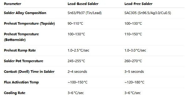
Lead-Based vs. Lead-Free Solder
Traditional lead-based solders, such as 63/37 tin-lead, melt at lower temperatures, around 183°C. However, during wave soldering, the pot temperature is set higher—typically 240°C to 250°C—to ensure proper flow and wetting. Lead-free solders, like SAC305 (tin-silver-copper), have a higher melting point of about 217°C to 221°C, requiring a pot temperature of 250°C to 260°C for optimal results.
Component Sensitivity
Not all components can withstand high temperatures. For instance, electrolytic capacitors and certain ICs may have maximum temperature ratings as low as 250°C. Exceeding this during wave soldering can lead to internal damage or reduced lifespan. Always check the datasheets of your components to ensure the selected wave soldering temperature range is safe.
Board Design and Material
The PCB material and thickness also influence temperature settings. Thicker boards or those with high copper content may require a slightly higher preheat temperature (closer to 150°C) to ensure even heating. FR-4, a common PCB material, can handle temperatures up to 260°C for short durations, but prolonged exposure risks delamination.
By balancing these factors, you can pinpoint the right temperature range for your specific assembly process, reducing the risk of defects and rework.
Optimal Wave Soldering Temperature for Lead-Free Solder
With the global shift to lead-free soldering due to environmental regulations like RoHS, finding the optimal wave soldering temperature for lead-free solder is more important than ever. Lead-free alloys, such as SAC305, require higher temperatures due to their elevated melting points. Here's how to optimize your setup for lead-free solder.
Recommended Temperature Settings
For most lead-free solders, set the solder pot temperature between 250°C and 260°C. This range ensures the solder flows properly and wets the surfaces without overheating components. During preheating, aim for 120°C to 150°C to minimize thermal shock, as lead-free soldering often involves a sharper temperature jump.
Challenges with Lead-Free Solder
Lead-free solder is less forgiving than lead-based alternatives. It has a narrower process window, meaning small deviations in temperature can lead to poor joints. For example, if the temperature drops below 250°C, you might see incomplete wetting or cold solder joints. Conversely, temperatures above 260°C increase the risk of component damage and solder oxidation.
Tips for Success
To achieve the best results with lead-free solder, monitor the solder pot temperature continuously using a calibrated thermometer. Adjust the conveyor speed to control contact time with the wave—2 to 3 seconds is often ideal. Additionally, use a nitrogen atmosphere if possible to reduce oxidation at higher temperatures.
Wave Soldering Temperature Effects on Components
The wave soldering temperature effects on components can be significant if not carefully managed. High temperatures or prolonged exposure can harm both the PCB and the components, leading to immediate failures or long-term reliability issues. Let's explore the most common effects and how to mitigate them.
Thermal Stress and Component Damage
Components like LEDs, capacitors, and microcontrollers often have strict temperature limits. For example, many surface-mount capacitors are rated for a maximum of 250°C for no more than 10 seconds. Exceeding this during wave soldering can cause internal cracks or degradation, leading to failures over time.
Solder Joint Defects
Incorrect temperatures can result in poor solder joints. If the solder wave is too cool (below 240°C for lead-based or 250°C for lead-free), the solder may not wet properly, creating cold joints that are mechanically weak. On the other hand, excessively high temperatures (above 260°C) can cause solder bridges between pads or excessive intermetallic growth, weakening the joint.
Related Reading: The Ultimate Guide to Wave Soldering Defects: Identification, Causes, and Prevention
Warp and Delamination of PCB
PCBs themselves are vulnerable to high temperatures. Prolonged exposure to temperatures above 260°C can cause the board material to warp or delaminate, especially in multi-layer designs. This not only affects the board's structural integrity but also disrupts the alignment of components and traces.
Mitigation Strategies
To minimize these risks, always tailor your wave soldering temperature profile to the most sensitive components on the board. Use thermal profiling tools to monitor the actual temperatures experienced by the PCB during the process. Additionally, consider selective soldering for boards with mixed technologies, where only specific areas are exposed to the solder wave.
Best Practices for Optimizing Wave Soldering Temperature
Now that we've covered the basics, here are some practical tips to fine-tune your wave soldering process for reliable results.
1. Use Thermal Profiling Tools
Invest in a thermal profiler to measure the temperature across different zones of your PCB during soldering. These tools provide real-time data, helping you adjust the preheat and solder wave temperatures to match the ideal profile.
2. Regularly Maintain Equipment
A well-maintained wave soldering machine ensures consistent temperatures. Check the solder pot for contamination and replenish flux as needed. Calibrate temperature sensors regularly to avoid drifts that could affect the wave soldering temperature range.
3. Test with Dummy Boards
Before running a full production batch, test your temperature settings with dummy boards. Inspect the solder joints for quality and check for any signs of component stress or board damage. Adjust the profile as needed based on these results.
4. Adjust Conveyor Speed
The speed at which the PCB passes over the solder wave affects exposure time. A slower speed increases contact time, which may be necessary for thicker boards but can overheat sensitive components. Aim for a contact time of 2 to 4 seconds as a starting point.
5. Document and Standardize Settings
Once you've found the optimal wave soldering temperature for lead-free solder or lead-based solder in your setup, document the settings. Standardizing the process reduces variability and helps maintain consistency across production runs.
Common Wave Soldering Defects Linked to Temperature Issues
Even with the best intentions, temperature-related defects can occur during wave soldering. Here are a few common issues and how to address them.
- Cold Solder Joints: Caused by insufficient temperature (below 240°C for lead-based or 250°C for lead-free). Increase the solder pot temperature or extend preheat time.
- Solder Bridges: Often due to excessive temperature or flux residue. Lower the solder wave height or temperature slightly and ensure proper flux application.
- Insufficient Wetting: Results from low temperature or poor flux activity. Verify the preheat temperature (120°C to 150°C) and check flux quality.
- Component Damage: Caused by temperatures exceeding component limits. Review datasheets and lower the solder pot temperature if needed.
By understanding these defects and their link to temperature, you can troubleshoot issues more effectively and improve overall soldering quality.
Conclusion: Perfecting Your Wave Soldering Temperature for Success
Optimizing the wave soldering temperature profile is a game-changer for achieving reliable PCB joints. Whether you're working within the wave soldering temperature range of 250°C to 260°C for lead-free solder or adjusting for sensitive components, precision is key. By carefully managing the wave soldering temperature effects on components and following best practices, you can minimize defects and boost the quality of your assemblies.
At ALLPCB, we understand the importance of precision in every step of PCB manufacturing. By applying the insights and tips from this guide, you'll be well on your way to mastering the optimal wave soldering temperature for lead-free solder and beyond. Fine-tune your process, monitor results, and watch your production quality soar.