 ALLPCB


If you're an engineer or electronics enthusiast struggling to understand capacitor markings, you're in the right place. Capacitor codes can seem like a cryptic puzzle, but they hold vital information about capacitance, voltage ratings, tolerance, and more. In this guide, we’ll break down capacitor marking codes, SMD capacitor identification, capacitor value lookup, EIA capacitor codes, and decipher capacitor symbols clearly and practically. Whether you're designing a circuit or troubleshooting a board, this comprehensive resource will help you master capacitor codes with ease.
Why Understanding Capacitor Codes Matters
Capacitors are fundamental components in electronics, used for energy storage, filtering, and stabilizing voltage in circuits. However, selecting the wrong capacitor due to misreading its markings can lead to circuit failure, reduced performance, or even safety hazards. For instance, using a capacitor with an insufficient voltage rating might cause it to break down under stress, while an incorrect capacitance value could disrupt signal timing in an oscillator circuit.
By learning to decode capacitor markings, you ensure precision in your designs and repairs. This guide is tailored for engineers who need actionable insights into identifying and interpreting these codes, especially for surface-mount devices (SMD) and traditional through-hole capacitors.
What Are Capacitor Codes and Markings?
Capacitor codes are a shorthand system used by manufacturers to label key specifications on the component’s body. Due to the small size of many capacitors, especially SMD types, there often isn’t enough space for full text. Instead, alphanumeric codes, color bands, or symbols are used to convey information like capacitance value, tolerance, and voltage rating.
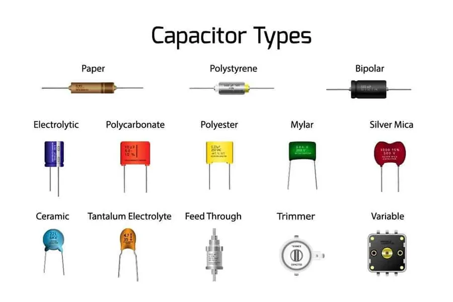
These markings vary depending on the type of capacitor—ceramic, electrolytic, tantalum, or film—and whether it’s an SMD or through-hole component. Understanding these differences is the first step in deciphering capacitor symbols and ensuring you’re using the right part for your project.
Types of Capacitor Markings
Let’s explore the common types of markings you’ll encounter and how to interpret them. This section covers both traditional and modern coding systems to help with capacitor value lookup.
1. Numeric and Alphanumeric Codes
Many capacitors, especially ceramic and film types, use a numeric or alphanumeric code to indicate capacitance. For example, a code like "104" on a ceramic capacitor means 10 followed by 4 zeros in picofarads (pF), which equals 100,000 pF or 0.1 microfarads (μF). The breakdown is simple:
- First two digits: Base value (10 in this case).
- Third digit: Multiplier (number of zeros to add, here it’s 4).
- Result: 10 with 4 zeros = 100,000 pF.
For tolerance and voltage, additional letters or numbers may follow. A letter like "K" often indicates a tolerance of ±10%, while a number or letter might denote voltage (e.g., "16" for 16V).
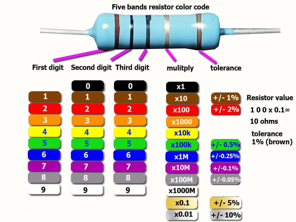
2. Color Codes
Older through-hole capacitors, especially tubular ceramics, often use color bands similar to resistors. Each color represents a digit or multiplier, and reading them requires a chart. For instance:
- First band (brown): 1
- Second band (black): 0
- Third band (red): Multiplier of 100
- Result: 10 x 100 = 1,000 pF or 1 nF.
Additional bands may indicate tolerance (±5% for gold) or temperature coefficient. While less common today, color codes are still relevant for vintage equipment repairs.
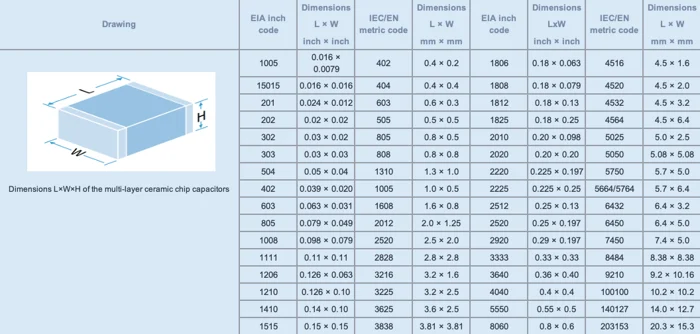
3. EIA Capacitor Codes for SMD Components
Surface-mount capacitors, widely used in compact modern designs, often follow the EIA capacitor codes system. Due to their tiny size, markings are minimal, typically a letter followed by a number. The letter represents the capacitance value, and the number indicates the multiplier. For example:
- "A5" means 1.0 (from "A") multiplied by 10^5, equaling 100,000 pF or 0.1 μF.
- "f9" means 5.0 (from "f") multiplied by 10^-1, equaling 0.5 pF.
However, not all SMD capacitors are marked—some rely on documentation or testing for SMD capacitor identification. In such cases, a capacitance meter is invaluable for verification.
Suggested Reading: Decoding SMD Resistor Codes: A Comprehensive Guide for Engineers
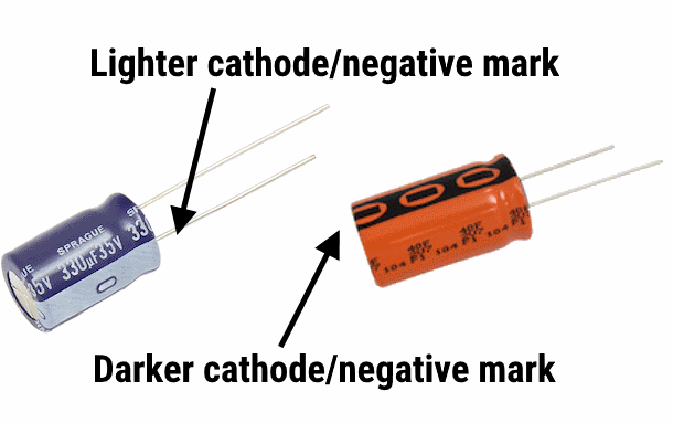
4. Polarity Markings on Electrolytic and Tantalum Capacitors
Electrolytic and tantalum capacitors are polarized, meaning they must be connected with the correct orientation. Incorrect polarity can cause catastrophic failure, including explosions in electrolytic types. Markings often include:
- A stripe or bar indicating the negative terminal.
- A "+" symbol near the positive lead on through-hole types.
- For SMD tantalum capacitors, a bar across one end often marks the positive side.
Always double-check polarity markings to avoid damaging your circuit.
How to Read Capacitor Markings: Step-by-Step
Now that we’ve covered the types of markings, let’s walk through a practical approach to capacitor marking codes. Follow these steps to decode any capacitor:
- Identify the Capacitor Type: Determine if it’s ceramic, electrolytic, tantalum, or another type. This narrows down the coding system.
- Look for Markings: Check for numbers, letters, color bands, or polarity indicators. For SMDs, markings might be absent, requiring documentation.
- Decode Capacitance: Use the numeric code (e.g., "104" = 0.1 μF) or EIA code (e.g., "A5" = 0.1 μF) to find the value.
- Check Tolerance and Voltage: Look for additional letters or numbers indicating tolerance (e.g., "K" = ±10%) and voltage rating (e.g., "50" = 50V).
- Verify Polarity (if applicable): For polarized capacitors, ensure you note the positive and negative terminals.
For quick reference, keep a chart or calculator tool handy for capacitor value lookup. Online resources and mobile apps can also assist in decoding complex markings.
Common Challenges in Decoding Capacitor Codes
Even with a solid understanding, engineers often face hurdles when interpreting capacitor markings. Here are some common issues and solutions:
1. Unmarked or Faded Markings
Especially with SMD capacitors or older components, markings may be missing or worn off. In such cases:
- Use a capacitance meter to measure the value directly.
- Refer to the circuit schematic or bill of materials (BOM) for specifications.
2. Non-Standard Codes
Some PCB manufacturers use custom markings not aligned with EIA standards. If documentation isn’t available, cross-reference with similar components or contact the supplier for clarification.
3. Misinterpreting Voltage Ratings
Voltage ratings are critical—using a capacitor rated for 10V in a 12V circuit can lead to failure. Always choose a capacitor with a voltage rating at least 20-30% higher than the circuit’s maximum voltage for safety. For example, in a 5V circuit, opt for a capacitor rated at 6.3V or higher.
Practical Applications: Using Capacitor Codes in Design and Repair
Understanding capacitor codes isn’t just academic—it directly impacts your work. Here are two real-world scenarios where this knowledge is essential:
Scenario 1: Designing a Power Supply Filter
In a power supply circuit, capacitors smooth out voltage ripples after rectification. Suppose you’re designing a 12V supply with a ripple current of 1A. You might select an electrolytic capacitor with a value of 1000 μF and a voltage rating of 16V to handle the load. By reading the marking "1000uF 16V" on the component, you confirm it meets the requirements. Misreading this as 100 μF could result in insufficient filtering, leading to unstable output.
Scenario 2: Troubleshooting a Faulty Circuit
During repair, you notice a failed SMD capacitor on a board. Its marking reads "B3," which, per EIA standards, translates to 1.1 μF (B = 1.1, 3 = 10^3). Testing with a multimeter confirms the capacitor is shorted. By decoding the marking, you can source a replacement with the same capacitance and voltage rating, ensuring the circuit functions correctly.
Tips for Mastering Capacitor Codes
To become proficient in deciphering capacitor symbols and codes, follow these practical tips:
- Keep Reference Materials Handy: Bookmark online calculators or print a chart for EIA codes and color bands.
- Invest in Tools: A capacitance meter or LCR meter can verify values when markings are unclear.
- Document Your Designs: When working with unmarked SMD capacitors, maintain detailed BOMs to avoid confusion during assembly or repair.
- Stay Updated: Manufacturers occasionally update coding systems, so check for the latest standards if you encounter unfamiliar markings.
Conclusion: Empowering Your Electronics Journey
Decoding capacitor codes doesn’t have to be a daunting task. With this guide, you now have a clear roadmap for capacitor marking codes explained, SMD capacitor identification, capacitor value lookup, and understanding EIA capacitor codes. By mastering these skills, you can confidently select the right components for your designs, troubleshoot issues effectively, and ensure the reliability of your circuits. Additionally, understanding capacitor specifications helps you optimize your BOM and better estimate custom PCB cost, especially when balancing performance with budget constraints in prototyping and production.


