 ALLPCB


In the fast-paced world of electronics, high-speed PCB design demands precision and care, especially when selecting passive components like resistors, capacitors, and inductors. For engineers and designers, the question often arises: how do you choose the right passive components to ensure signal integrity and performance in high-speed circuits? The answer lies in understanding the nuances of component behavior, such as parasitic inductance in capacitors, resistor tolerance on PCBs, and their impact on high-frequency signals. This PCB passive component selection guide will walk you through the critical factors to consider for high-speed PCB design, helping you avoid common pitfalls and optimize your circuits.
In this detailed blog, we’ll dive deep into the essentials of selecting passive components for high-speed applications. From managing parasitic effects to understanding tolerance and impedance, we’ll cover actionable tips and insights to elevate your PCB designs. Whether you’re a seasoned engineer or just starting out, this guide will equip you with the knowledge to master component selection and achieve reliable, high-performance results.
Why Passive Component Selection Matters in High-Speed PCB Design
High-speed PCBs operate at frequencies where even the smallest details can significantly impact performance. Signals traveling at gigahertz speeds—often exceeding 1 GHz—can be distorted by parasitic effects, impedance mismatches, and component tolerances. Passive components, though seemingly simple, play a critical role in maintaining signal integrity, filtering noise, and ensuring power delivery. A poor choice in a capacitor or resistor can introduce unwanted noise, crosstalk, or signal delays, leading to system failures.
For instance, in a high-speed digital circuit, a capacitor with high parasitic inductance might fail to decouple noise effectively at frequencies above 100 MHz. Similarly, a resistor with wide tolerance could skew voltage divider outputs, affecting logic levels. By prioritizing a strategic approach to component selection, you can mitigate these risks and build robust designs tailored for high-speed environments.
Understanding Parasitic Effects in Passive Components
At high frequencies, passive components exhibit parasitic behaviors that deviate from their ideal characteristics. These effects—parasitic inductance in capacitors, parasitic capacitance in inductors, and equivalent series resistance (ESR)—can degrade performance if not accounted for. Let’s break down these effects and how they influence high-speed PCB design.
Parasitic Inductance in Capacitors
Capacitors are essential for decoupling and filtering in high-speed designs, but they aren’t perfect. Every capacitor has a small amount of parasitic inductance, often in the range of 0.5 to 2 nH, due to its leads and internal structure. This parasitic inductance capacitor effect becomes problematic at high frequencies, where it causes the capacitor to behave more like an inductor, reducing its ability to filter noise or stabilize voltage.
To minimize this, opt for capacitors with low equivalent series inductance (ESL). Surface-mount multilayer ceramic capacitors (MLCCs) in smaller packages, such as 0402 or 0603, often have lower ESL compared to larger sizes. Additionally, placing capacitors close to the power pins of ICs—ideally within 0.1 inches—reduces trace inductance and enhances decoupling efficiency.
Parasitic Capacitance in Inductors
Inductors, used in power supply filtering and RF circuits, suffer from parasitic capacitance between their windings. At high frequencies, this capacitance can create a parallel resonance, allowing unwanted signals to pass through. For high-speed designs, choose inductors with a high self-resonant frequency (SRF), ensuring it exceeds your operating frequency. For example, if your circuit operates at 500 MHz, select an inductor with an SRF above 1 GHz to avoid resonance issues.
Equivalent Series Resistance (ESR)
ESR in capacitors and inductors introduces power losses and affects filtering performance. In high-speed designs, low-ESR capacitors are critical for maintaining stable power delivery to ICs. A capacitor with high ESR might cause voltage ripples, especially in switching power supplies operating at 1 MHz or higher. Always check the datasheet for ESR values—aim for capacitors with ESR below 0.1 ohms for optimal results.
Resistor Tolerance and Its Impact on High-Speed PCBs
Resistors might seem straightforward, but their tolerance plays a significant role in resistor tolerance PCB applications, especially in high-speed circuits. Tolerance indicates how much a resistor’s actual value can deviate from its nominal value, typically expressed as a percentage. Common tolerances range from 1% to 5%, but in precision circuits, even a 1% deviation can cause issues.
For example, in a voltage divider used for signal conditioning in a 2.5 GHz communication system, a resistor with 5% tolerance could shift the output voltage by up to 50 mV, potentially causing signal misinterpretation. To avoid this, use resistors with 1% or 0.1% tolerance for critical applications. Additionally, consider temperature coefficient of resistance (TCR), as resistors can drift with temperature changes—aim for TCR values below 50 ppm/°C for stability in varying conditions.
Another factor is power rating. High-speed circuits often involve rapid switching, generating heat. Ensure resistors can handle the power dissipation without overheating, as this can alter resistance values and degrade performance. A general rule is to select a resistor with a power rating at least twice the expected dissipation; for instance, if your circuit dissipates 0.25 W, choose a 0.5 W resistor.
Key Factors in PCB Passive Component Selection for High-Speed Designs
Selecting the right passive components for high-speed PCBs involves balancing multiple parameters. This PCB passive component selection guide outlines the most critical factors to consider during the design process.
Frequency Response and Impedance Matching
In high-speed designs, components must maintain their performance across the operating frequency range. Capacitors and inductors should be chosen based on their impedance at the target frequency. For instance, a decoupling capacitor for a 1 GHz signal should have low impedance—ideally below 1 ohm—at that frequency. Use manufacturer datasheets or simulation tools to verify impedance curves and ensure compatibility with your design.
Impedance matching is equally important to prevent signal reflections. In RF circuits operating at 2.4 GHz, mismatched impedance can cause a standing wave ratio (SWR) greater than 1.5, leading to signal loss. Select resistors and other components that align with the characteristic impedance of your transmission lines, typically 50 ohms in RF applications.
Package Size and Mounting Inductance
Smaller component packages, such as 0201 or 0402, are often preferred in high-speed designs due to their lower parasitic inductance. However, extremely small packages can be harder to assemble and may increase manufacturing costs. Strike a balance by choosing a package size that minimizes parasitic effects while ensuring reliable soldering. For instance, 0402 capacitors often offer a good compromise, with mounting inductance around 0.6 nH compared to 1.2 nH for 0805 packages.
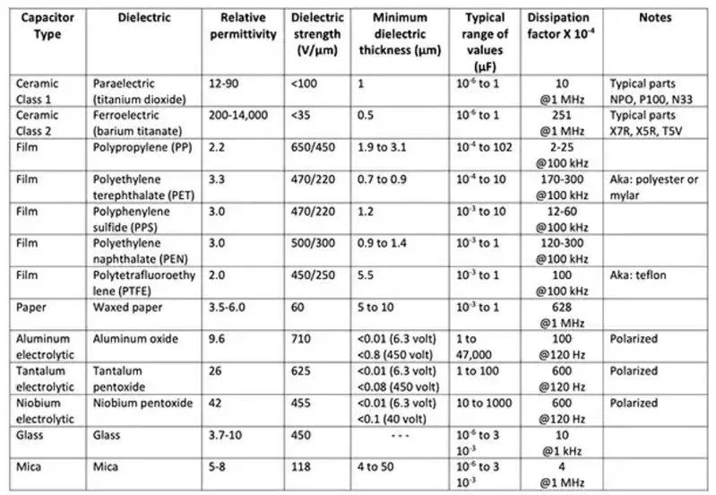
Material and Dielectric Properties
For capacitors, the dielectric material affects performance at high frequencies. X7R and X5R ceramics are popular for decoupling due to their stability over temperature, though they may exhibit capacitance reduction under DC bias. For high-frequency filtering, consider NP0/C0G capacitors, which have minimal capacitance variation and low loss, ideal for signals above 500 MHz.
Practical Tips for High-Speed PCB Layout with Passive Components
Component selection is only half the battle; proper placement and layout are just as crucial in high-speed PCB design. Here are some practical tips to optimize your design:
- Minimize Trace Lengths: Keep traces between components and IC pins as short as possible to reduce parasitic inductance. For decoupling capacitors, aim for trace lengths under 0.1 inches to maintain low impedance paths.
- Use Ground Planes: A solid ground plane beneath high-speed signals reduces electromagnetic interference (EMI) and provides a low-impedance return path. Avoid splitting ground planes under critical components to prevent signal loops.
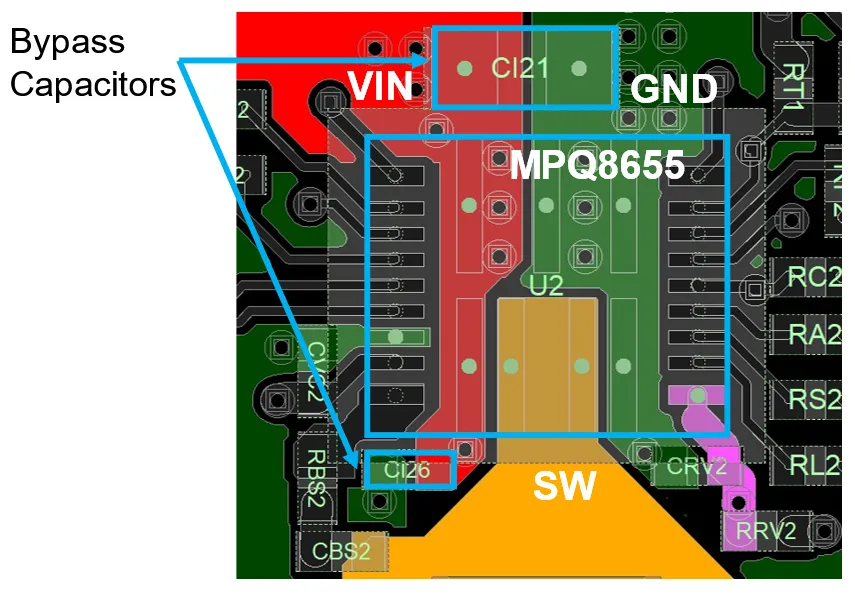
- Place Decoupling Capacitors Strategically: Position decoupling capacitors near the power pins of ICs, with smaller value capacitors (e.g., 0.1 μF) closest to the pin for high-frequency noise filtering, followed by larger values (e.g., 10 μF) for bulk capacitance.
- Avoid Via Inductance: Excessive vias in high-speed paths add inductance, often around 1 nH per via. Minimize via usage or use multiple vias in parallel to reduce effective inductance.
Common Mistakes to Avoid in Passive Component Selection
Even experienced designers can make errors in component selection. Here are some pitfalls to watch out for:
- Ignoring Parasitic Effects: Failing to account for parasitic inductance or capacitance can lead to unexpected signal behavior. Always review component datasheets for ESL, ESR, and SRF values.
- Overlooking Tolerance: Using resistors or capacitors with wide tolerance in precision circuits can introduce errors. Stick to tight tolerances (1% or better) for critical applications.
- Neglecting Temperature Effects: Components can drift with temperature, affecting performance. Choose parts with low temperature coefficients to ensure stability in varying environments.
- Improper Component Sizing: Selecting components with insufficient power ratings or incorrect package sizes can lead to overheating or assembly issues. Double-check specifications against design requirements.
Tools and Resources for Component Selection
Navigating the vast array of passive components can be daunting, but several tools can simplify the process. Online component libraries and simulation software allow you to model parasitic effects and test component behavior in virtual circuits. Many manufacturers provide detailed datasheets and impedance graphs to aid in selection. Additionally, PCB design software often includes features to analyze signal integrity and power distribution, helping you validate your choices before fabrication.
For high-speed designs, consider using SPICE simulations to evaluate how components interact with your circuit at different frequencies. These simulations can reveal issues like resonance or impedance mismatches early in the design phase, saving time and cost during prototyping.
Conclusion: Building Better High-Speed PCBs with Smart Component Choices
Mastering passive component selection is a cornerstone of successful high-speed PCB design. By understanding the impact of parasitic effects like parasitic inductance capacitor behavior, prioritizing resistor tolerance PCB considerations, and following best practices for layout, you can create circuits that perform reliably even at multi-gigahertz frequencies. This PCB passive component selection guide has provided a roadmap to navigate these challenges, offering practical tips and insights to enhance your designs.
As technology continues to push the boundaries of speed and complexity, staying informed about component characteristics and design strategies will keep you ahead of the curve. With careful selection and attention to detail, your high-speed PCBs can achieve optimal signal integrity, minimal noise, and robust performance for any application.


