 ALLPCB


Introduction
Flexible PCB connectors serve as critical interfaces between flexible printed circuits and rigid boards or other components in modern electronics. These interconnects accommodate the dynamic bending and movement inherent to flexible PCBs, making them essential in applications like consumer wearables, automotive sensors, and medical devices. Selecting the appropriate flexible PCB connector type ensures signal integrity, mechanical stability, and long-term performance under stress. Engineers face challenges in balancing space constraints, electrical demands, and environmental factors during flexible PCB connector selection. This article explores flexible PCB connector types, key selection criteria, reliability considerations, and soldering practices to guide informed decisions. By understanding these elements, you can troubleshoot common issues and optimize designs for demanding environments.
What Are Flexible PCB Connectors and Why They Matter
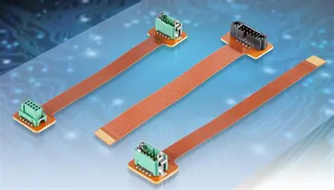
Flexible PCB connectors link flat flexible cables or flexible printed circuits to host boards, enabling compact, lightweight assemblies. They differ from rigid connectors by incorporating mechanisms that handle repeated flexing without fatigue. Common configurations include surface-mount types on rigid PCBs that mate with gold-plated fingers on the flex tail. In high-density designs, these connectors support pitches as fine as 0.3 mm, facilitating miniaturization. Their importance stems from the growing use of flexible circuits in space-limited products where traditional wiring fails due to bulk and rigidity. Poor connector choice leads to intermittent contacts, signal loss, or mechanical failures, directly impacting product reliability.
The mechanics rely on precise contact pressure to maintain electrical continuity during motion. Actuation methods like flip-up lids or sliding locks secure the flex tail, preventing dislodgement from vibration. Engineers must evaluate mating cycles, typically ranging from hundreds to thousands, based on application needs. Flexible PCB connector reliability becomes paramount in harsh conditions, such as automotive under-hood modules exposed to temperature swings and moisture. Adhering to established guidelines prevents common pitfalls like insertion damage or corrosion. Ultimately, these connectors bridge the gap between flexible innovation and robust system performance.
Flexible PCB Connector Types
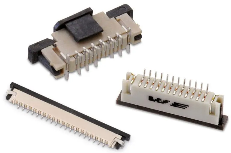
Flexible PCB connector types primarily fall into zero insertion force, low insertion force, and solder-based categories, each suited to specific mechanical and electrical requirements. Zero insertion force connectors feature a clamping mechanism that opens to accept the flex tail with minimal pressure, then locks to apply uniform contact force. This design reduces wear on fine-pitch gold fingers, ideal for high-cycle applications like displays in portable devices. Low insertion force variants require slight manual push for mating but offer higher retention without actuators, balancing ease and security. Flat flexible cable connectors handle ribbon-style cables with insulation displacement contacts, providing quick assembly for power distribution.
Solder-type flexible PCB connectors integrate pads directly onto the flex circuit for permanent attachment to rigid boards, eliminating mechanical mating. Board-to-flex options mount on the host PCB and accept flex tails, supporting pitches from 0.5 mm to 1.25 mm commonly. Insulation displacement connectors pierce cable insulation for solderless termination, useful in prototyping or low-cost builds. Each type influences flexible PCB connector selection based on space, cost, and rework needs. Troubleshooting tip: mismatched pitch leads to misalignment, so verify specifications early in design.
Related Reading: Understanding Connector Types: A Comprehensive Guide for PCB Design
Key Factors in Flexible PCB Connector Selection
Flexible PCB connector selection hinges on pitch compatibility, ensuring the flex tail aligns perfectly with receptacle contacts to avoid bridging or open circuits. Common pitches include 0.3 mm for ultra-fine applications and 1.0 mm for general use, dictating density and signal count. Insertion force and retention strength determine suitability for automated assembly or hand mating, with low-force types preferred for delicate flex materials. Current-carrying capacity and impedance control matter for high-speed signals, where gold plating thickness enhances conductivity and corrosion resistance. Environmental ratings cover operating temperatures, humidity, and chemical exposure, critical for outdoor or industrial gear.
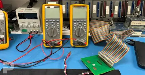
Mechanical cycle life addresses repeated mating in test fixtures or user-accessible ports, guiding choices between robust clamps and simpler designs. Cable thickness and conductor orientation, same-side or opposite-side, must match connector specs to ensure full contact. Vibration and shock resistance favors connectors with locking features, preventing fretting corrosion. Cost and availability factor into volume production, but prioritize performance to avoid field failures. Always prototype to validate flexible PCB connector selection under real conditions.
Related Reading: Connector Choices: DFM Considerations for Flex PCB Interconnects
Enhancing Flexible PCB Connector Reliability
Flexible PCB connector reliability depends on material choices like phosphor bronze contacts with selective gold plating for low resistance and oxidation prevention. Design per IPC-2223 guidelines ensures flex tail stiffness supports insertion without buckling. Testing protocols simulate end-use stresses, including thermal cycling and bend radius evaluations to detect fatigue early. Vibration testing reveals contact stability, while humidity exposure checks for creep corrosion. Gold finger flatness and plating adhesion prevent intermittent opens during flexing.
Assembly cleanliness removes flux residues that accelerate dendrite growth, maintaining low contact resistance over time. IPC-6013 qualification verifies performance across classes, from consumer to high-reliability aerospace. Troubleshooting common issues involves inspecting for actuator wear or tail contamination. Implementing strain relief near the connector reduces stress concentration. Regular audits confirm compliance, extending service life in dynamic applications.
Best Practices for Flexible PCB Connector Soldering
Flexible PCB connector soldering applies to surface-mount receptacles or direct flex pad attachments, demanding precise thermal profiles to avoid delamination. Preheat the assembly to minimize shock, following J-STD-001 requirements for ramp rates and peak temperatures. Reflow soldering suits high-volume production, with nitrogen atmospheres reducing oxidation on fine-pitch leads. Hot bar bonding joins flex tails to pads using anisotropic conductive film, applying controlled pressure and heat pulses. Hand soldering risks overheating polyimide substrates, so use fine tips and flux sparingly.
Post-solder inspection per IPC-A-610 criteria checks fillet formation, wetting, and voiding to predict joint integrity. Avoid excessive flux that traps moisture, leading to popcorn effects in reflow. Strain relief epoxies secure soldered areas against peel forces. Profile verification with thermocouples ensures consistency across boards. These practices enhance joint reliability, minimizing rework in flexible PCB connector soldering.
Conclusion
Choosing the right flexible PCB connector involves evaluating types, selection criteria, reliability factors, and soldering techniques for optimal performance. ZIF and LIF dominate for their balance of ease and durability, while soldered options suit permanent links. Prioritize pitch match, environmental resilience, and standards compliance to sidestep common failures. Practical testing and clean assembly practices solidify designs. Engineers benefit from iterative prototyping to refine flexible PCB connector selection. This approach delivers robust interconnects for innovative flexible electronics.
FAQs
Q1: What are the main flexible PCB connector types?
A1: ZIF connectors use a zero-force insertion with flip actuators for high-density, fine-pitch applications. LIF types require minimal push for secure mating, ideal for moderate cycles. FFC connectors handle ribbon cables via insulation displacement, and solder types provide permanent bonds. Selection depends on pitch, cycles, and assembly method for reliable performance.
Q2: How do you approach flexible PCB connector selection for high-reliability applications?
A2: Assess pitch, insertion force, current rating, and cycle life first. Consider environmental factors like temperature and vibration. Test prototypes for signal integrity and mechanical retention. Follow IPC-6013 for qualification to ensure durability. Balance cost with performance to avoid field issues in demanding uses.
Q3: What impacts flexible PCB connector reliability in dynamic environments?
A3: Contact materials, plating quality, and strain relief primarily affect longevity. Vibration causes fretting, while humidity promotes corrosion. IPC-2223 design rules mitigate flex fatigue. Regular testing like thermal cycling identifies weaknesses early. Clean assembly prevents residue-induced failures.
Q4: What are best practices for flexible PCB connector soldering?
A4: Use controlled reflow profiles per J-STD-001 to prevent substrate damage. Apply strain relief post-solder. Inspect joints against IPC-A-610 for voids and wetting. Preheat adequately and minimize flux. Hot bar for ACF bonds ensures uniform pressure.
References
IPC-6013 — Qualification and Performance Specification for Flexible Printed Boards. IPC.
IPC-2223 — Sectional Design Standard for Flexible Printed Boards. IPC.
J-STD-001 — Requirements for Soldered Electrical and Electronic Assemblies. IPC/JEDEC.
IPC-A-610 — Acceptability of Electronic Assemblies. IPC.


