 ALLPCB


Introduction
Selecting the right materials for a PCB batch is a critical decision that directly influences the performance, reliability, and cost-effectiveness of the final product. Electrical engineers often face the challenge of balancing electrical properties, thermal management, and mechanical stability when specifying substrates for batch production. Poor material choices can lead to signal degradation, thermal failures, or warpage issues during assembly and operation. In high-volume batches, material consistency becomes even more vital to ensure uniformity across panels and minimize yield losses. This guide explores PCB material selection batch strategies, focusing on FR-4 PCB batch applications, high-frequency PCB materials, and PCB substrate comparisons to help engineers make informed decisions. By understanding key properties and industry benchmarks, you can optimize your designs for real-world demands.
Understanding PCB Substrates and Their Role in Batch Production
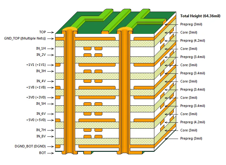
PCB substrates form the foundational structure of any printed circuit board, consisting primarily of a dielectric core and prepreg layers that bond copper foils. These materials must provide electrical insulation while supporting traces and components under varying stresses. In batch production, substrates need to exhibit consistent thickness, resin content, and weave patterns to avoid variations that could affect etching or lamination processes. FR-4 remains the most common substrate due to its balance of properties, making it ideal for standard FR-4 PCB batch runs in consumer electronics and industrial controls. However, for specialized applications, alternatives offer superior performance in specific areas. Engineers must evaluate substrates based on the entire manufacturing flow, from lamination to reflow soldering.
The relevance of substrate selection intensifies in batch contexts because large panels amplify any material inconsistencies, potentially leading to widespread defects. For instance, mismatched coefficients of thermal expansion between substrate and copper can cause delamination during thermal cycling. Industry standards like IPC-4101 classify base materials into specification sheets, ensuring suppliers meet defined criteria for resin systems and reinforcements. This standardization supports reliable PCB material selection batch processes by providing a common language for procurement. Ultimately, the right substrate aligns with the application's electrical frequency, power dissipation, and environmental exposure, preventing costly rework in production.
Key Properties of PCB Materials: A Technical Breakdown
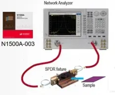
Several core properties determine a substrate's suitability for PCB applications, starting with dielectric constant and dissipation factor, which govern signal propagation and loss. A stable dielectric constant minimizes impedance variations, crucial for controlled impedance traces in multilayer boards. Dissipation factor indicates energy loss as heat, becoming problematic at higher frequencies where even small increases degrade signal integrity. Thermal properties, such as glass transition temperature, define the material's stability above soldering temperatures, while coefficient of thermal expansion matches components to reduce stress. Mechanical strength, including tensile modulus and peel strength, ensures board rigidity and copper adhesion during handling and assembly.
Moisture absorption affects reliability, as absorbed water can lower insulation resistance or cause popcorning during reflow. In high-frequency PCB materials, low moisture uptake is essential to maintain consistent electrical performance in humid environments. IPC-6012E outlines qualification tests for rigid printed boards, including thermal shock and humidity exposure, to verify material robustness. For batch production, materials with low z-axis expansion prevent via barrel cracking in thick multilayers. Engineers should prioritize substrates with balanced profiles, avoiding trade-offs that compromise overall board life.
High-frequency PCB materials differ markedly from standard epoxies by incorporating fluoropolymers or ceramic fillers to achieve low loss tangents. These materials maintain stable permittivity across a broad frequency range, unlike epoxies that exhibit rising losses above 1 GHz. Reinforcement styles, such as spread glass or low-profile weaves, further reduce signal skew in high-speed designs. In contrast, FR-4 excels in mechanical robustness but shows increased attenuation in microwave bands. Understanding these mechanisms allows precise PCB substrate comparison during design reviews.
Related Reading: Beyond FR-4: Choosing High-Performance PCB Materials for Extended Lifespan
PCB Substrate Comparison: FR-4, High-Frequency, and Specialized Options
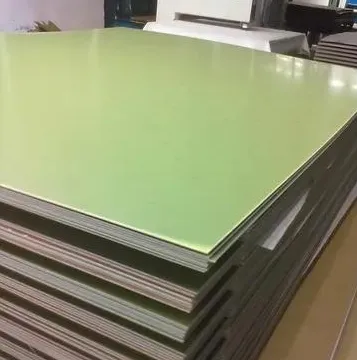
When conducting a PCB substrate comparison, FR-4 sets the baseline as a glass-reinforced epoxy laminate with versatile properties for general-purpose boards. It offers good dimensional stability, flame retardancy per UL 94 V-0 equivalent, and compatibility with standard fabrication flows. For FR-4 PCB batch production, engineers benefit from its availability in various thicknesses and copper weights, supporting high yields in volume runs. However, its moderate dielectric properties limit use in demanding RF applications.
High-frequency PCB materials prioritize minimal signal loss, featuring lower dissipation factors and controlled dielectric constants. These substrates often use polytetrafluoroethylene bases or hybrid composites, providing superior performance beyond 5 GHz for radar, telecom, and 5G infrastructure. They demand specialized processing, such as adjusted drilling parameters to handle softer resins, which impacts batch costs. Polyimides serve harsh environments with high thermal resistance, ideal for aerospace where continuous operation exceeds 200 degrees Celsius.
- FR-4 — Key strengths: Cost-effective, mechanically strong, easy to process; Typical applications: Power supplies, automotive controls; Considerations for batch: Standard for high-volume, monitor Tg for lead-free assembly.
- High-Frequency — Key strengths: Low loss, stable Dk/Df over frequency; Typical applications: RF antennas, high-speed data; Considerations for batch: Higher cost, ensure supplier consistency.
- High-Tg Epoxy — Key strengths: Elevated thermal stability; Typical applications: Multilayer with heavy copper; Considerations for batch: Improved warpage control in thick stacks.
- Polyimide — Key strengths: Extreme temperature range; Typical applications: Military, downhole sensors; Considerations for batch: Limited availability, higher moisture sensitivity.
This table aids quick PCB substrate comparison, highlighting trade-offs in cost versus performance.
Metal-clad substrates, like those for LED lighting, incorporate aluminum or copper bases for heat spreading but require careful CTE matching. Each type suits specific needs, with FR-4 dominating cost-sensitive batches.
Related Reading: FR4 Material Explained in PCB Manufacturing
Best Practices for PCB Material Selection in Batch Production
Start material selection by defining application requirements: operating frequency, power levels, and environmental factors like humidity or vibration. For frequencies below 1 GHz, FR-4 suffices in most FR-4 PCB batch scenarios, but transition to high-frequency PCB materials above that threshold to preserve signal quality. Consult IPC-4101 specification sheets to match your needs, such as /101 for standard FR-4 or /126 for high-Tg variants. Request material data sheets verifying compliance, including test coupons for CTE and Tg.
In batch planning, prioritize suppliers with proven traceability and lot-to-lot consistency to avoid panel warpage or drill smear. Simulate thermal profiles using finite element analysis to predict stresses, adjusting stackups accordingly. For high-frequency designs, hybrid stacks blending FR-4 cores with low-loss skins optimize cost while meeting performance. Implement design for manufacturability by specifying panel sizes that align with material formats, reducing waste.
Qualification testing per IPC-6012E ensures batches withstand accelerated life cycles. Monitor fabrication yields post-prototype, iterating on material grades if delamination occurs. Collaborate early with fabricators to validate high-frequency PCB materials compatibility with their equipment.
Common Pitfalls and Troubleshooting in Material Selection
One frequent issue is underestimating moisture effects, leading to reflow failures; bake boards pre-assembly per JEDEC J-STD-020 guidelines. Warpage in thick multilayers stems from asymmetric builds; symmetrize stackups and select low-CTE high-Tg materials. For high-frequency batches, inconsistent dielectric thickness causes impedance mismatches; specify tight tolerances and verify with TDR measurements.
Troubleshoot by analyzing cross-sections for resin voids or fiber prominence. If signal loss exceeds expectations, audit dissipation factor across frequencies. These factory-driven insights prevent recurrence in future PCB material selection batch runs.
Conclusion
Choosing materials for your PCB batch demands a systematic approach weighing electrical, thermal, and mechanical demands against cost and manufacturability. FR-4 excels in standard applications, while high-frequency PCB materials unlock advanced capabilities, as revealed through PCB substrate comparisons. Adhering to standards like IPC-4101 and IPC-6012E ensures reliability across production scales. By integrating these principles, electrical engineers can deliver robust boards that perform consistently in the field. Prioritize data-driven decisions to streamline your next batch.
FAQs
Q1: What factors should guide PCB material selection batch for high-volume production?
A1: Key factors include operating frequency, thermal cycling requirements, and cost per panel. For FR-4 PCB batch runs, ensure IPC-4101 compliance for uniformity. High-frequency needs demand low-loss substrates to minimize attenuation. Balance these with supplier lead times to avoid delays.
Q2: How does FR-4 compare to high-frequency PCB materials in performance?
A2: FR-4 offers excellent mechanical strength and affordability for low-to-mid frequencies but higher losses above 1 GHz. High-frequency PCB materials provide stable dielectrics and low dissipation for RF applications. Select based on signal speed; hybrids often bridge gaps cost-effectively.
Q3: Why is consistency critical in PCB substrate comparison for batches?
A3: Batch consistency prevents variations in thickness or properties that cause etching defects or warpage. IPC-6012E testing verifies performance uniformity. Poor matching leads to yield drops; always qualify lots with coupons.
Q4: When should engineers opt for alternatives to standard FR-4 in batches?
A4: Choose alternatives for extreme temperatures, high power, or GHz signals where FR-4 limits emerge. High-Tg or polyimide suits harsh environments. Perform PCB substrate comparison early to align with assembly processes.
References
IPC-4101E — Specification for Base Materials for Rigid and Multilayer Printed Boards. IPC, 2017
IPC-6012E — Qualification and Performance Specification for Rigid Printed Boards. IPC, 2017
JEDEC J-STD-020E — Moisture/Reflow Sensitivity Classification. JEDEC, 2014


