 ALLPCB


If you're venturing into the world of electronics projects and wondering how to master SMD soldering on 3D printed PCBs, you're in the right place. This beginner-friendly guide will walk you through the essentials of soldering tiny surface-mount components onto custom 3D-printed circuit boards. Whether you're working on DIY electronics projects or just starting with a soldering tutorial, we'll simplify the process with step-by-step instructions, tools, and tips to ensure success.
In this detailed blog, we'll cover everything from the basics of SMD components to creating and soldering on 3D printed PCBs. By the end, you'll have the confidence to tackle how to solder SMD components and bring your innovative ideas to life. Let's dive in!
What Are SMD Components and 3D Printed PCBs?
Before we get into the hands-on part of this soldering tutorial, let’s clarify the basics. Surface-Mount Device (SMD) components are small electronic parts designed to be soldered directly onto the surface of a circuit board, unlike traditional through-hole components that require holes to be drilled. SMDs are compact, making them ideal for modern, space-saving designs in electronics projects.
On the other hand, 3D printed PCBs are custom circuit boards created using additive manufacturing technology. Instead of relying on traditional PCB fabrication, you can design and print a board with conductive traces using specialized filaments or inks, or even create a base structure and add conductive paths manually. These are perfect for prototyping and DIY electronics projects where flexibility and creativity are key.
Combining SMD soldering with 3D printed PCBs allows hobbyists and engineers to create highly customized, lightweight, and innovative designs. However, the process can seem daunting at first. That’s why this guide will break down SMD soldering on 3D printed PCBs into manageable steps.
Why Use 3D Printed PCBs for SMD Soldering?
Traditional PCBs are great for mass production, but 3D printed PCBs offer unique advantages for beginners and hobbyists working on DIY electronics projects. Here are a few reasons why they’re worth considering:
- Customization: You can design a PCB to fit any shape or size using 3D modeling software, perfect for unconventional projects.
- Rapid Prototyping: Print a prototype in hours instead of waiting days or weeks for a manufactured board.
- Cost-Effective for Small Runs: Ideal for one-off designs or small batches without the high costs of traditional PCB production.
- Learning Tool: Experimenting with 3D printed PCBs is a low-risk way to learn how to solder SMD components and test circuit ideas.
However, 3D printed PCBs often have limitations like lower conductivity compared to copper-clad boards (typically around 0.1-1 S/m for conductive filaments versus 5.96 × 10^7 S/m for copper) and less durability under high temperatures. This makes precision and care during soldering even more critical.
Tools and Materials for SMD Soldering on 3D Printed PCBs
To get started with SMD soldering on 3D printed PCBs, you’ll need the right tools and materials. Here’s a comprehensive list tailored for beginners:
- Soldering Iron: A fine-tip soldering iron (15-30W) with adjustable temperature control. Set it between 260-300°C for SMD work to avoid damaging components or melting the 3D printed material.
- Solder: Use lead-free solder wire with a diameter of 0.5-0.8mm for precision.
- Flux: Helps the solder flow smoothly and prevents oxidation. Opt for a no-clean flux pen for ease of use.
- Tweezers: Precision tweezers for handling tiny SMD components.
- Magnifying Glass or Microscope: Essential for seeing small pads and components clearly.
- Desoldering Braid: Useful for correcting mistakes by removing excess solder.
- 3D Printer and Filament: For printing the PCB base. Use standard PLA or PETG for the structure, and conductive filament if embedding traces.
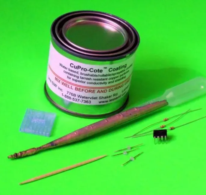
- Conductive Paint or Ink: If your printer doesn’t support conductive filament, use this to draw traces on the printed board.
- Multimeter: To test connections and ensure continuity after soldering.
- SMD Components: Resistors, capacitors, LEDs, or ICs depending on your project.
Step-by-Step Guide: SMD Soldering on 3D Printed PCBs
Now that you have your tools ready, let’s walk through the process of how to solder SMD components onto a 3D printed PCB. Follow these steps carefully for the best results.
Step 1: Design and Print Your PCB
Start by designing your circuit layout using software like KiCad or Fritzing. Export the design as a 3D model if you’re printing the board structure. Ensure the pads for SMD components are appropriately sized (typically 0.8-1.2mm wide for small components like 0805 resistors).
Print the PCB using a 3D printer. If using conductive filament, align the traces during printing. Otherwise, print a non-conductive base and prepare to add conductive paths manually. Keep the layer height low (around 0.1-0.2mm) for smoother surfaces that make soldering easier.
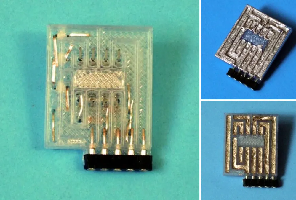
Step 2: Create Conductive Traces
If your 3D printed PCB doesn’t have embedded conductive traces, use conductive paint or ink to draw the circuit paths. Apply the paint with a fine brush or pen, ensuring even coverage. Let it dry completely (usually 1-2 hours) before proceeding. Test the traces with a multimeter to confirm conductivity—aim for resistance below 10 ohms per centimeter for reliable performance.
Step 3: Prepare Your Soldering Station
Set up your soldering iron at a temperature of 260-280°C for most SMD components. Higher temperatures (above 300°C) risk melting the 3D printed material, especially if it’s PLA with a melting point of around 180-220°C. Clean the iron tip with a damp sponge or brass wire cleaner to ensure it’s free of residue.
Apply a small amount of flux to the PCB pads where components will be placed. Flux improves solder adhesion and reduces the risk of cold joints, which can cause unreliable connections.
Step 4: Place and Solder SMD Components
Using tweezers, carefully place the SMD component onto the prepared pads. For a two-lead component like a resistor or capacitor, follow these steps:
- Add a small dab of solder to one pad.
- Position the component on the pads, aligning one end with the soldered pad.
- Heat the soldered pad and place the component end into the molten solder. Hold it steady until the solder cools (2-3 seconds).
- Solder the other end by applying solder and the iron tip to the pad and component lead simultaneously. Avoid excess solder to prevent bridging.
For larger components like ICs with multiple pins, apply solder to one corner pin first to anchor the component, then solder the remaining pins. Use minimal heat exposure—limit contact to 1-2 seconds per pin to avoid damaging the 3D printed base.
Step 5: Inspect and Test Your Work
After soldering, inspect the joints under a magnifying glass. Look for shiny, smooth solder joints without cracks or bridges between pads. Use a multimeter to test for continuity between connected points and ensure there are no short circuits.
If you spot a mistake, use desoldering braid and flux to remove excess solder. Heat the braid over the joint to absorb the solder, then reposition or replace the component as needed.
Tips for Successful SMD Soldering on 3D Printed PCBs
Soldering tiny components on a non-traditional board can be tricky. Here are some practical tips to improve your results in DIY electronics projects:
- Work in a Well-Ventilated Area: Soldering produces fumes, so ensure proper ventilation or use a fume extractor.
- Practice First: Before working on your actual project, practice soldering SMD components on a scrap piece of material or a test PCB.
- Use Low-Melting-Point Solder: If your 3D printed PCB material is heat-sensitive, consider solder with a lower melting point (around 180-200°C) to reduce the risk of damage.
- Keep Components Secure: Use a small dot of adhesive or double-sided tape to hold components in place before soldering, especially for multi-pin parts.
- Avoid Overheating: Limit soldering time on each joint to prevent warping or melting the printed board. If needed, let the board cool between soldering sessions.
Common Challenges and How to Overcome Them
Beginners often face hurdles when learning how to solder SMD components on 3D printed PCBs. Here are some common issues and solutions:
- Warped or Melted PCB: This happens if the soldering iron is too hot or applied for too long. Use a lower temperature (260°C) and work quickly. If warping occurs, consider reprinting the board with a more heat-resistant material like PETG.
- Poor Conductivity in Traces: Conductive paints or filaments often have higher resistance. Double-check connections with a multimeter and reinforce weak traces with additional conductive material if necessary.
- Solder Bridges: If solder connects two adjacent pads, use desoldering braid to remove the excess. Applying flux beforehand can help prevent this issue.
- Component Misalignment: SMD parts are tiny and can shift during soldering. Use tweezers for precise placement and secure them before soldering.
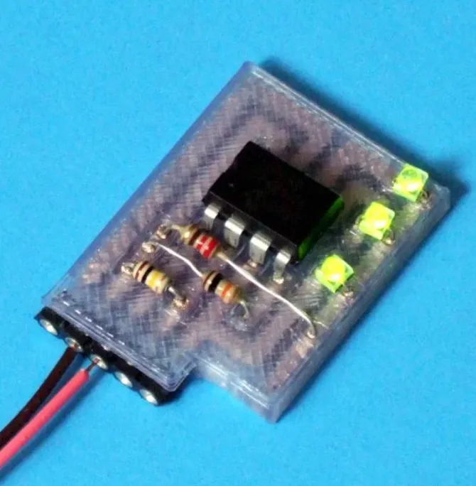
Project Idea: Build a Simple LED Circuit on a 3D Printed PCB
To put your new skills to the test, try this beginner-friendly project. Create a small LED blinker circuit using SMD components on a 3D printed PCB. Here’s a quick overview:
- Design a simple circuit with a 555 timer IC, a few SMD resistors (e.g., 1kΩ and 10kΩ in 0805 size), a capacitor (0.1μF), and an SMD LED.
- Print a small rectangular PCB base (5cm x 3cm) with space for the components.
- Draw or print conductive traces connecting the components as per the circuit schematic.
- Solder the SMD components using the steps outlined above.
- Power the circuit with a 5V supply and watch the LED blink at a frequency determined by the resistor and capacitor values (approximately 1-2 Hz).
This project is a great way to practice SMD soldering on 3D printed PCBs while creating something functional for your electronics projects.
Conclusion: Mastering SMD Soldering on 3D Printed PCBs
Learning SMD soldering on 3D printed PCBs opens up a world of possibilities for DIY electronics projects. While it may seem challenging at first, with the right tools, techniques, and patience, you can achieve professional-looking results even as a beginner. This soldering tutorial has covered the essentials—from designing and printing your PCB to soldering tiny components and troubleshooting common issues.
Start small, practice often, and experiment with different designs to build your confidence. As you grow more comfortable with how to solder SMD components, you’ll be able to tackle more complex electronics projects and bring your creative ideas to life. Keep exploring, and let your innovation shine!


