ALLPCB


In the world of high-speed electronics, maintaining signal integrity is crucial for ensuring that devices function reliably. One key factor in achieving this is through proper PCB impedance testing. But why does it matter? Simply put, PCB impedance testing ensures that signals travel through a circuit board without distortion, interference, or loss, which is vital for performance in modern electronics. In this comprehensive guide, we’ll dive deep into the importance of impedance control PCB testing, explore methods like TDR impedance measurement, and explain how these practices contribute to PCB signal integrity testing. Whether you’re an engineer or a designer, understanding these concepts will help you build better, more reliable products.
What Is PCB Impedance and Why Does It Matter?
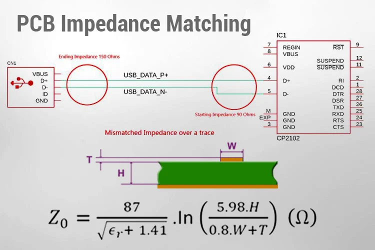
Impedance in a printed circuit board (PCB) refers to the resistance a signal encounters as it travels along a trace. Unlike simple resistance, impedance includes both resistive and reactive components, influenced by factors like frequency, trace geometry, and the materials used in the PCB. When impedance isn’t properly managed, signals can reflect, distort, or lose strength, leading to errors in data transmission or complete system failure.
In high-speed designs, such as those found in telecommunications, computing, and automotive systems, even small impedance mismatches can cause significant issues. For example, a mismatch in a 5G communication board operating at frequencies above 1 GHz can result in signal delays or data corruption. This is why controlled impedance PCB manufacturing is a critical step in modern electronics production. By testing and controlling impedance, manufacturers ensure that signals remain intact from source to destination.
The Role of Signal Integrity in PCB Design
Signal integrity refers to the quality and reliability of an electrical signal as it travels through a PCB. Poor signal integrity can lead to issues like crosstalk, electromagnetic interference (EMI), and signal reflection. These problems are especially common in high-speed circuits where signals switch at rates of several gigahertz. PCB signal integrity testing, which includes impedance testing, helps identify and mitigate these risks before they impact performance.
For instance, in a differential pair used for high-speed data transfer (like USB or HDMI), maintaining consistent impedance is essential to prevent signal skew—where one signal in the pair arrives later than the other. A typical target impedance for differential pairs might be 100 ohms, with a tolerance of ±10%. If this value deviates due to manufacturing inconsistencies, the system could fail to meet performance standards. This is where differential impedance testing comes into play, ensuring that paired traces maintain their intended characteristics.
Understanding Impedance Control in PCB Manufacturing
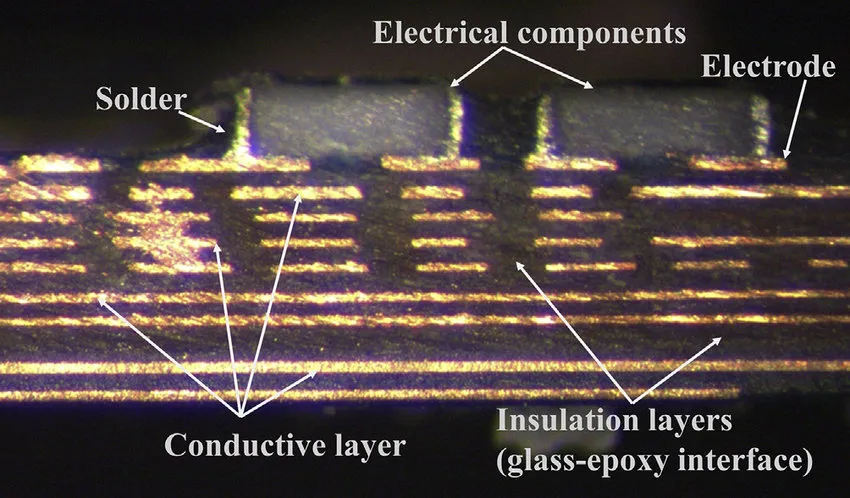
Controlled impedance PCB manufacturing is the process of designing and fabricating boards to meet specific impedance values. This involves careful selection of materials, precise trace layouts, and consistent dielectric thicknesses. For example, a common dielectric material like FR4 has a dielectric constant (Dk) of around 4.2 to 4.5, which affects how signals propagate. Designers use this information to calculate trace widths and spacing to achieve the desired impedance, often targeting values like 50 ohms for single-ended traces or 100 ohms for differential pairs.
However, design alone isn’t enough. Variations in manufacturing—such as uneven copper thickness or deviations in dielectric properties—can alter impedance. This is why impedance testing is a critical quality control step. By verifying that the fabricated board matches the design specifications, manufacturers can guarantee reliable performance in the final product.
Methods of PCB Impedance Testing
There are several techniques for measuring impedance on a PCB, each suited to different stages of design and production. Below, we explore some of the most common methods used in impedance control PCB testing.
Time Domain Reflectometry (TDR) Impedance Measurement
One of the most widely used methods for impedance testing is Time Domain Reflectometry, or TDR. TDR impedance measurement works by sending a fast electrical pulse down a trace and measuring the reflections that occur due to impedance mismatches. The time it takes for the reflection to return, along with the amplitude of the reflected signal, helps determine the impedance at specific points along the trace.
For example, if a trace is designed for 50 ohms but a section measures 60 ohms due to a manufacturing defect, TDR will detect this mismatch as a deviation in the reflection pattern. This method is highly accurate and can pinpoint issues down to fractions of a millimeter, making it ideal for high-speed designs. TDR is often used during both prototype testing and final quality assurance to ensure consistent impedance across the board.
Frequency Domain Testing
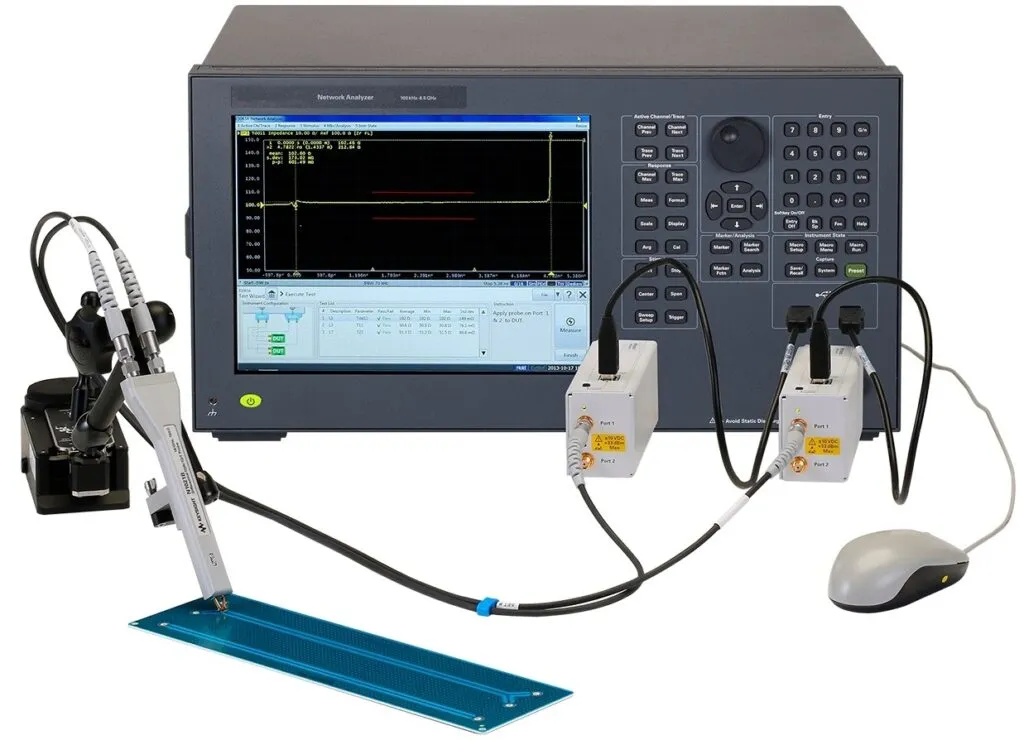
Another approach is frequency domain testing, which measures impedance across a range of frequencies using specialized equipment like vector network analyzers (VNAs). This method is particularly useful for applications like RF circuits, where impedance can vary with frequency. For instance, a PCB designed for a 2.4 GHz Wi-Fi module might show acceptable impedance at lower frequencies but exhibit mismatches at the target frequency. Frequency domain testing helps identify such issues early in the design phase.
Differential Impedance Testing
For designs involving differential pairs, differential impedance testing is essential. This method measures the impedance between two traces in a pair, ensuring that they maintain a consistent value (often 90 to 120 ohms, depending on the standard). Specialized test fixtures and equipment are used to simulate real-world conditions, allowing engineers to verify that the pair operates without signal skew or interference. This is critical for protocols like PCIe, Ethernet, and USB, where differential signaling is common.
Why Impedance Testing Is Crucial for Signal Integrity
Impedance mismatches can have a cascading effect on signal integrity, leading to several undesirable outcomes. Here are some of the key reasons why PCB impedance testing is non-negotiable for high-speed designs:
- Preventing Signal Reflections: When a signal encounters an impedance mismatch, part of it reflects back toward the source, causing interference. This can degrade signal quality and lead to data errors. Testing ensures that impedance remains consistent, minimizing reflections.
- Reducing Crosstalk: In densely packed PCBs, signals on adjacent traces can interfere with each other, especially if impedance isn’t controlled. Proper testing helps maintain spacing and impedance values to reduce crosstalk.
- Ensuring Timing Accuracy: In high-speed systems, even small delays caused by impedance variations can disrupt timing. For example, in a DDR4 memory interface operating at 3200 MT/s, a delay of just a few picoseconds can cause data corruption. Impedance testing helps maintain timing accuracy.
- Meeting Industry Standards: Many industries, such as automotive and telecommunications, have strict standards for signal integrity. Impedance testing ensures compliance with these requirements, avoiding costly redesigns or failures in the field.
Challenges in Impedance Control and Testing
While the importance of impedance testing is clear, achieving consistent results isn’t always straightforward. Several challenges can arise during controlled impedance PCB manufacturing and testing:
- Material Variations: Dielectric constants and copper thickness can vary between batches, affecting impedance. Rigorous material selection and testing are needed to minimize these inconsistencies.
- Trace Geometry: Small deviations in trace width or spacing—sometimes as little as 0.1 mm—can alter impedance. Precision manufacturing and testing are essential to catch these issues.
- Environmental Factors: Temperature and humidity can influence dielectric properties, leading to impedance shifts over time. Testing under simulated operating conditions helps address this challenge.
- Complex Designs: Modern PCBs often include multiple layers, high-density interconnects, and mixed-signal designs, making impedance control more difficult. Advanced testing methods like TDR and differential impedance testing are critical for these boards.
Best Practices for Effective PCB Impedance Testing
To ensure reliable results from PCB signal integrity testing, engineers and manufacturers should follow these best practices:
- Start with Accurate Design Calculations: Use simulation tools to model impedance based on trace dimensions, stackup, and material properties. Target specific values like 50 ohms for single-ended traces or 100 ohms for differential pairs.
- Collaborate with Fabricators: Work closely with your manufacturing partner to define impedance tolerances (e.g., ±10%) and ensure they have the capability to meet these specs.
- Use TDR for Validation: Incorporate TDR impedance measurement during prototyping and production to verify that actual boards match design goals.
- Test Under Real Conditions: Perform differential impedance testing and frequency domain analysis under conditions that mimic the final application, accounting for factors like temperature and signal frequency.
- Document Results: Keep detailed records of impedance test results for traceability and to address any issues that arise during production or field use.
How Impedance Testing Impacts Product Reliability
The ultimate goal of impedance testing is to enhance the reliability of electronic products. A well-tested PCB with controlled impedance can withstand the demands of high-speed operation, resist environmental stresses, and deliver consistent performance over time. For example, in a medical device like a patient monitor, signal integrity issues caused by impedance mismatches could lead to inaccurate readings, endangering lives. By prioritizing PCB impedance testing, manufacturers can prevent such failures and build trust in their products.
Moreover, thorough testing reduces the need for costly redesigns and recalls. A single batch of PCBs with impedance issues could result in thousands of defective units, leading to significant financial losses. Investing in controlled impedance PCB manufacturing and testing upfront saves time, money, and reputation in the long run.
Conclusion: Prioritizing Impedance Testing for Better PCBs
In today’s fast-paced electronics industry, signal integrity is more important than ever. PCB impedance testing plays a vital role in ensuring that signals travel without distortion, maintaining the performance and reliability of high-speed systems. From TDR impedance measurement to differential impedance testing, these methods help catch issues early, prevent signal degradation, and meet strict industry standards.
Whether you’re designing a cutting-edge smartphone or a critical automotive system, understanding and implementing impedance control PCB testing is essential. By focusing on controlled impedance PCB manufacturing and rigorous testing practices, you can create products that stand out for their quality and dependability. At ALLPCB, we’re committed to supporting engineers with the tools and expertise needed to achieve optimal signal integrity in every project.