 ALLPCB


Are you looking to design a flexible printed circuit board (PCB) that can withstand dynamic bending or fit into a tight, compact space? The key lies in choosing the right flex PCB thickness and materials. For dynamic bending, a thinner flex PCB—often between 0.1 mm to 0.3 mm—paired with durable materials like polyimide is ideal. Polyimide thickness for flex circuits typically ranges from 12.5 μm to 50 μm, balancing flexibility and strength. When it comes to material selection for flexible PCBs, polyimide stands out for its thermal stability and mechanical durability, though other options like polyester can work for less demanding applications.
In this comprehensive guide, we’ll explore the nuances of flex PCB thickness for dynamic bending, the ideal polyimide thickness for flex circuits, and the critical factors in material selection for flexible PCBs. Whether you're an engineer working on wearable tech or designing for aerospace applications, this blog will help you make informed decisions for your next project.
What Are Flex PCBs and Why Do They Matter?
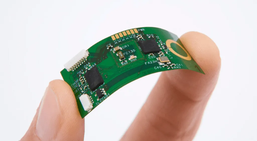
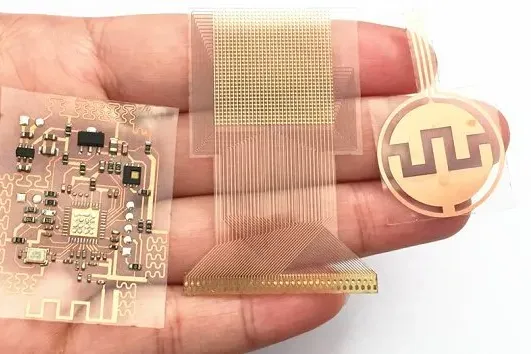
Flexible PCBs, or flex circuits, are a type of printed circuit board that can bend, fold, or twist without breaking. Unlike traditional rigid PCBs, flex circuits are built on flexible substrates, allowing them to conform to unique shapes or fit into tight spaces. They’re widely used in industries like consumer electronics (think smartphones and wearables), medical devices, automotive systems, and aerospace technology.
The magic of flex PCBs lies in their ability to reduce weight, save space, and improve reliability in dynamic environments. However, achieving these benefits requires careful consideration of thickness and material choices. Let’s dive into how these factors impact performance and durability.
Flex PCB Thickness for Dynamic Bending: Finding the Sweet Spot
When designing a flex PCB for dynamic bending—where the board will repeatedly flex during use—thickness is one of the most critical factors. A thinner PCB is generally more flexible, but it must still provide enough structural integrity to avoid cracking or tearing under stress.
Why Thickness Matters for Dynamic Bending
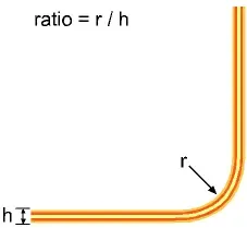
The thickness of a flex PCB directly affects its bend radius, which is the tightest curve the board can handle without damage. A thinner board can achieve a smaller bend radius, making it ideal for applications like foldable devices or robotics. However, if the board is too thin, it risks mechanical failure or reduced electrical performance due to weakened traces.
For dynamic bending, the typical flex PCB thickness range from 0.1 mm to 0.3 mm. A single-layer flex circuit might be as thin as 0.1 mm, while multilayer designs for more complex applications might reach up to 0.3 mm. As a rule of thumb, the IPC-2223 standard (a widely recognized guideline for flex PCB design) suggests that the bend radius should be at least 10 times the thickness of the board for dynamic applications to minimize stress on copper traces.
Balancing Thickness with Durability
While thinner boards are more flexible, they can be less durable under constant bending. For instance, a 0.1 mm thick flex PCB might handle a bend radius of 1 mm, but repeated bending cycles—say, 100,000 or more in a wearable device—could lead to trace fatigue. To counter this, designers often add stiffeners or reinforcements in high-stress areas without increasing overall thickness.
Polyimide Thickness for Flex Circuits: Striking the Right Balance
Polyimide is the go-to material for most flex circuits due to its excellent flexibility, thermal resistance, and mechanical strength. But when it comes to polyimide thickness for flex circuits, there’s no one-size-fits-all answer. The thickness of the polyimide substrate must align with the specific demands of your application.
Common Polyimide Thickness Ranges
Polyimide substrates are typically available in thicknesses ranging from 12.5 μm (0.5 mil) to 50 μm (2 mil). Thinner polyimide layers, such as 12.5 μm or 25 μm, are often used in applications requiring high flexibility, like in compact consumer electronics. Thicker layers, closer to 50 μm, provide more durability and are better suited for environments with higher mechanical stress or thermal exposure, such as automotive or aerospace systems.
For dynamic bending, a polyimide thickness of 25 μm is often a sweet spot. It offers enough flexibility for a tight bend radius while maintaining sufficient strength to prevent cracking over thousands of flex cycles. For static flex applications—where the board is bent once and stays in place—thicker polyimide layers can be used to enhance reliability.
Impact on Electrical and Thermal Performance
The thickness of polyimide also affects the electrical and thermal properties of the flex circuit. Thinner polyimide layers reduce the dielectric constant, which can improve signal integrity for high-speed applications (e.g., frequencies above 1 GHz). However, they may also have lower thermal dissipation, potentially leading to overheating in high-power designs. For example, a 25 μm polyimide layer might handle temperatures up to 260°C, but pushing beyond this with high current loads could degrade performance if not paired with proper heat management.
Material Selection for Flexible PCBs: Beyond Polyimide
While polyimide dominates the flex PCB world, material selection for flexible PCBs involves considering other options based on cost, performance, and environmental factors. Let’s break down the key materials and when to use them.
Polyimide: The Gold Standard
Polyimide is favored for its balance of flexibility, thermal stability (up to 260°C or higher), and chemical resistance. It’s ideal for dynamic bending and harsh environments, such as in medical implants or satellite systems. Its tensile strength, often around 165 MPa, ensures it can withstand repeated flexing without tearing. However, polyimide can be more expensive than other materials, so it’s not always the best choice for budget-conscious projects.
Polyester (PET): A Cost-Effective Alternative
For less demanding applications, polyester (PET) is a viable alternative. It’s cheaper than polyimide and still offers decent flexibility, with thicknesses typically ranging from 25 μm to 125 μm. However, PET has lower thermal resistance (around 120°C) and is less durable under dynamic bending. It’s often used in static flex applications, like in calculators or simple displays, where the board is bent once during assembly and remains fixed.
Adhesive vs. Adhesiveless Laminates
Another consideration in material selection is whether to use adhesive or adhesiveless laminates. Traditional flex PCBs use adhesives to bond copper to the substrate, but these can degrade under high temperatures or repeated bending. Adhesiveless laminates, where copper is directly bonded to the substrate, offer better flexibility and thermal performance. For dynamic bending, adhesiveless polyimide laminates are often recommended, as they reduce the risk of delamination after thousands of flex cycles.
Key Factors in Designing with Flex PCB Thickness and Materials
Beyond just choosing the right thickness and material, several design considerations can make or break the performance of your flex PCB. Here are some practical tips to keep in mind.
Layer Count and Stack-Up Design
The number of layers in a flex PCB impacts its thickness and flexibility. Single-layer designs are the thinnest and most flexible, often around 0.1 mm total thickness, while multilayer designs (up to 6 layers or more) can reach 0.3 mm or thicker. When designing for dynamic bending, minimize the number of layers to maintain flexibility, and use staggered vias to reduce stress points.
Copper Weight and Trace Design
The weight of copper used in the flex PCB—typically ranging from 0.5 oz (17 μm) to 2 oz (70 μm)—affects both thickness and durability. For dynamic bending, lighter copper weights like 0.5 oz are preferred to reduce stiffness. Additionally, design traces to run perpendicular to the bend axis, and avoid placing vias or components in high-stress bend areas to prevent cracking.
Environmental Considerations
The operating environment plays a big role in material selection. For high-temperature applications (above 200°C), polyimide with adhesiveless laminates is essential. In humid or corrosive environments, ensure the material has low moisture absorption (polyimide typically absorbs less than 1.5% moisture) to prevent swelling or degradation.
Common Challenges and Solutions in Flex PCB Design
Designing flex PCBs isn’t without its challenges, especially when optimizing for thickness and materials. Here are some common issues and how to address them.
Cracking Under Dynamic Bending
Repeated bending can cause copper traces or the substrate to crack, especially if the bend radius is too tight. To mitigate this, use a larger bend radius (at least 10x the board thickness) and opt for rolled annealed copper, which is more flexible than standard electrodeposited copper. Adding PCB stiffeners in non-bending areas can also help distribute stress.
Thermal Management Issues
Thinner flex PCBs and polyimide layers can struggle to dissipate heat in high-power applications. To solve this, incorporate thermal vias or heat sinks where possible, and consider using thicker copper layers (up to 2 oz) in areas that don’t require bending to improve heat conduction.
Cost Constraints
High-performance materials like polyimide and adhesiveless laminates can drive up costs. If budget is a concern, consider hybrid designs that combine polyimide in dynamic areas with cheaper materials like polyester in static sections. This approach balances performance and affordability.
Conclusion: Mastering Flex PCB Design for Your Needs
Designing a flex PCB that performs reliably under dynamic bending or in challenging environments starts with understanding flex PCB thickness and material selection. For dynamic bending, aim for a total thickness between 0.1 mm and 0.3 mm to achieve a tight bend radius without sacrificing durability. When choosing polyimide thickness for flex circuits, a range of 25 μm to 50 μm often provides the best mix of flexibility and strength. And in material selection for flexible PCBs, polyimide remains the top choice for most applications, though polyester can be a cost-effective alternative for static designs.
By carefully considering these factors—along with layer count, copper weight, and environmental conditions—you can create flex circuits that meet the demands of your project, whether it’s a compact wearable or a rugged automotive system. With the right design choices, you’ll unlock the full potential of flexibility in your PCB designs.


