 ALLPCB


Designing a battery charger PCB that performs efficiently while managing heat is a critical challenge for engineers. Effective thermal management ensures reliability, extends component life, and prevents failures in battery charger systems. In this comprehensive guide, we’ll explore the essentials of battery charger PCB thermal design, focusing on heat dissipation in PCBs, the role of thermal vias in PCBs, strategic component placement for thermal performance, and the importance of PCB material thermal conductivity. Whether you're a seasoned engineer or just starting, this guide offers practical insights to optimize your designs for heat management.
Why Thermal Management Matters in Battery Charger PCBs
Battery chargers, especially those for high-power applications like electric vehicles or fast-charging mobile devices, generate significant heat during operation. Components such as power transistors, diodes, and voltage regulators can reach temperatures exceeding 100°C if not properly managed. Excessive heat can degrade performance, cause thermal runaway, or even lead to catastrophic failures. Effective thermal management in PCB design helps maintain safe operating temperatures, typically below 85°C for most components, ensuring long-term reliability and safety.
In the following sections, we’ll break down the key strategies to achieve optimal thermal performance in battery charger PCBs, from layout techniques to material selection.
Understanding Heat Dissipation in PCBs for Battery Chargers
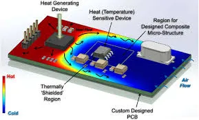
Heat dissipation in PCBs is the process of transferring heat away from critical components to prevent overheating. In battery charger designs, heat is primarily generated by power components during the charging process. If this heat isn’t dissipated effectively, it can lead to hotspots, where localized temperatures exceed safe limits, often above 120°C for certain ICs.
To manage heat dissipation, designers must focus on several factors:
- Copper Planes: Using large copper areas on the PCB acts as a heat sink, spreading heat across a wider surface. For instance, a 2 oz copper layer can handle higher thermal loads compared to a 1 oz layer, reducing temperature rise by up to 20% in high-current areas.
- Board Thickness: Thicker boards, such as 2.0 mm compared to standard 1.6 mm, can improve heat spreading due to increased material volume.
- Airflow: Designing for natural or forced convection by leaving space around heat-generating components can lower temperatures by 10-15°C in some cases.
By prioritizing these elements in your PCB layout, you can significantly reduce thermal stress on components, ensuring a more robust battery charger design.
The Role of Thermal Vias in PCB Design
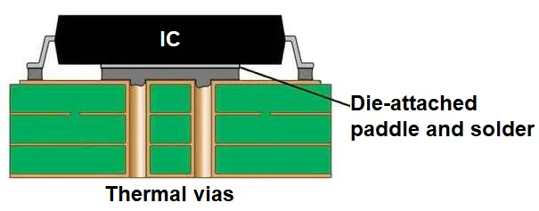
Thermal vias in PCBs are small, plated-through holes that transfer heat from one layer of the board to another, typically from a component’s thermal pad to a copper plane or heat sink on the opposite side. In battery charger PCBs, thermal vias are crucial for managing heat from high-power components like MOSFETs, which can dissipate 5-10 watts of power in compact areas.
Here’s how to use thermal vias effectively:
- Placement: Position thermal vias directly under or near the thermal pads of heat-generating components. A grid of 0.3 mm diameter vias spaced 1.2 mm apart can reduce thermal resistance by up to 30%.
- Quantity: More vias mean better heat transfer. For a component dissipating 8 watts, using 10-15 vias can lower the junction temperature by approximately 5-10°C.
- Connection: Connect vias to large copper planes on multiple layers to maximize heat spreading. Ensure the vias are filled or capped to prevent solder wicking during assembly.
Thermal vias are a cost-effective way to enhance heat dissipation without adding external cooling solutions, making them a go-to strategy in compact battery charger designs.
Strategic Component Placement for Thermal Performance
Component placement for thermal performance is a critical aspect of battery charger PCB design. Poor placement can create hotspots, where heat from multiple components accumulates, pushing temperatures beyond safe limits (often above 100°C for sensitive parts).
Consider these best practices for optimal placement:
- Spacing: Place high-power components, such as inductors and power ICs, away from each other to avoid heat concentration. A spacing of at least 5-10 mm can prevent thermal overlap.
- Proximity to Edges: Position heat-generating parts near board edges or areas with better airflow to facilitate natural convection cooling.
- Orientation: Align components like diodes and transistors to allow heat to dissipate evenly across copper traces. For example, aligning a TO-220 package parallel to a large copper plane can reduce thermal resistance by 15%.
- Avoid Sensitive Areas: Keep temperature-sensitive components, such as microcontrollers, away from heat sources. A safe distance of 15 mm or more can prevent performance degradation.
By carefully planning component placement, you can minimize thermal issues and improve the overall reliability of your battery charger PCB.
Choosing the Right PCB Material for Thermal Conductivity
The choice of PCB material significantly impacts PCB material thermal conductivity, which determines how effectively heat is conducted away from components. Standard FR-4 material, commonly used in PCBs, has a thermal conductivity of about 0.25 W/m·K, which is often insufficient for high-power battery charger applications.
For better thermal performance, consider these material options:
- High-Tg FR-4: With a thermal conductivity of around 0.3-0.4 W/m·K, this variant of FR-4 offers slightly better heat transfer and can withstand higher temperatures (up to 150°C) without degrading.
- Metal-Core PCBs (MCPCBs): These boards feature a metal base, often aluminum, with a thermal conductivity of 1-2 W/m·K. They are ideal for battery chargers with power dissipation exceeding 10 watts, reducing component temperatures by up to 20°C compared to standard FR-4.
- Ceramic-Based Materials: With thermal conductivities ranging from 20-30 W/m·K, ceramic substrates are excellent for extreme heat dissipation but come at a higher cost. They are often used in specialized high-power chargers.
Selecting a material with higher thermal conductivity can drastically improve heat management, especially in compact designs where space for additional cooling solutions is limited. However, balance cost and performance needs when choosing materials, as advanced options can increase manufacturing expenses by 30-50%.
Additional Thermal Management Techniques for Battery Charger PCBs
Beyond the core strategies discussed, several additional techniques can enhance thermal management in battery charger PCBs:
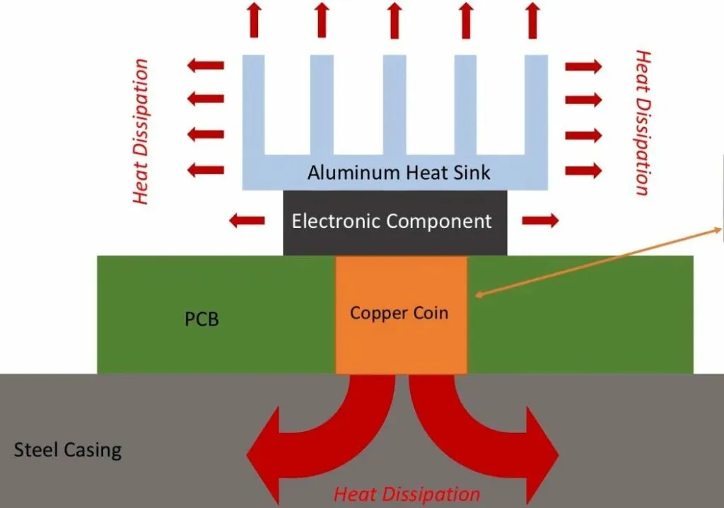
- Heat Sinks: Attach heat sinks to high-power components to increase surface area for heat dissipation. A small aluminum heat sink can reduce component temperature by 15-25°C under load.
- Thermal Pads and Compounds: Use thermal interface materials between components and heat sinks or PCB surfaces to improve heat transfer efficiency by up to 40%.
- Multi-Layer Designs: Utilize multiple PCB layers with dedicated ground and power planes to distribute heat more evenly. A 4-layer board can reduce thermal resistance by 10-20% compared to a 2-layer design.
- Active Cooling: In high-power applications, consider integrating small fans or liquid cooling systems. Forced airflow can lower temperatures by 20-30°C in densely packed designs.
Combining these techniques with the core strategies of thermal vias, component placement, and material selection creates a robust thermal management system tailored to your battery charger’s specific needs.
Thermal Simulation and Testing for Battery Charger PCBs
Before finalizing your design, thermal simulation and testing are essential to validate performance. Software tools can model heat distribution and identify potential hotspots in your PCB layout. These tools often predict temperature rises with an accuracy of ±5°C under typical operating conditions.
Follow these steps for effective thermal analysis:
- Simulation: Input power dissipation values (e.g., 5 watts for a power IC) and material properties into the simulation tool to visualize heat flow. Adjust layouts based on areas exceeding safe temperature limits, such as 85°C for most components.
- Prototyping and Testing: Build a prototype and use infrared cameras to measure actual temperatures during operation. Compare these results with simulation data to refine your design.
- Iterate: Make iterative changes, such as adding more thermal vias or adjusting component spacing, until temperatures are within acceptable ranges.
Investing time in simulation and testing can save costly redesigns and ensure your battery charger PCB operates reliably under real-world conditions.
Conclusion: Building Efficient Battery Charger PCBs with Thermal Management
Thermal management is a cornerstone of effective battery charger PCB thermal design. By focusing on heat dissipation in PCBs through techniques like copper planes and airflow, leveraging thermal vias in PCBs for heat transfer, optimizing component placement for thermal performance, and selecting materials with high PCB material thermal conductivity, you can create designs that are both efficient and reliable.
Start with a solid layout plan, incorporate thermal vias where needed, and choose materials that match your power and budget requirements. Don’t forget to validate your design with simulations and real-world testing to catch potential issues early. With these strategies, you’ll be well-equipped to tackle the thermal challenges of battery charger PCB design, ensuring long-lasting performance for your applications.
At ALLPCB, we’re committed to supporting engineers with resources and manufacturing solutions to bring your designs to life. Apply these thermal management principles in your next project to achieve optimal results.


