 ALLPCB


Are you searching for the best ultra-thin PCB materials for your next project? Whether you're designing compact electronics or high-performance devices, selecting the right substrate is critical. In this guide, we'll explore the top materials like FR4 thin PCB, polyimide thin PCB, and BT material thin PCB, while diving into key factors such as dielectric constant for thin PCB designs. You'll get a clear understanding of each option, their properties, and how to choose the perfect substrate for your needs.
At ALLPCB, we understand the importance of precision and performance in printed circuit board design. This comprehensive guide will walk you through everything you need to know about ultra-thin PCB materials, ensuring your designs are both efficient and reliable. Let's dive in!
What Are Ultra-Thin PCB Materials?
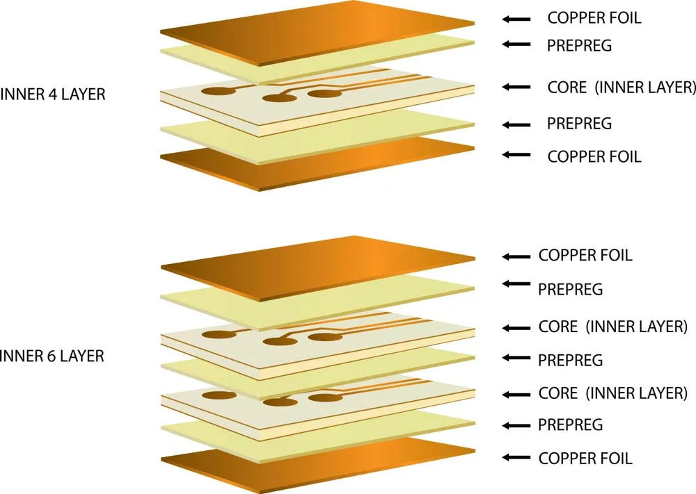
Ultra-thin PCB materials are specialized substrates used in printed circuit boards (PCBs) where space and weight are major constraints. These materials typically have a thickness of less than 0.5 mm, sometimes as low as 0.1 mm, making them ideal for compact devices like smartphones, wearables, and medical equipment. The primary goal of using ultra-thin materials is to reduce the overall size of the PCB while maintaining electrical performance and mechanical stability.
Choosing the right ultra-thin PCB material involves balancing factors like flexibility, thermal resistance, dielectric properties, and cost. Common materials include FR4 thin PCB for standard applications, polyimide thin PCB for flexible and high-temperature needs, and BT material thin PCB for advanced, high-frequency designs. In the following sections, we'll break down each material and help you decide which one suits your project best.
Key Factors to Consider When Choosing Ultra-Thin PCB Materials
Before diving into specific materials, it's important to understand the properties that impact the performance of ultra-thin PCBs. Here are the main factors to keep in mind:
- Thickness: Ultra-thin PCBs are defined by their minimal thickness, often below 0.5 mm. Thinner materials save space but may compromise mechanical strength.
- Dielectric Constant (Dk): This measures a material's ability to store electrical energy. A lower dielectric constant in thin PCB designs is better for high-frequency applications as it reduces signal loss. For example, a Dk of 2.5-3.0 is ideal for high-speed signals, while higher values like 4.4-4.8 (common in FR4) may cause delays.
- Thermal Resistance: Materials must withstand heat during operation and manufacturing processes like soldering. High-temperature tolerance is crucial for reliability.
- Flexibility: Some applications require bendable PCBs, making flexible substrates like polyimide a top choice.
- Cost: Budget constraints often influence material selection. Balancing performance with affordability is key.
With these factors in mind, let's explore the most popular ultra-thin PCB materials and their unique advantages.
FR4 Thin PCB: The Affordable and Reliable Choice
FR4 is one of the most widely used materials in PCB manufacturing due to its cost-effectiveness and versatility. FR4 thin PCB refers to ultra-thin variants of this material, often ranging from 0.2 mm to 0.5 mm in thickness. Made from woven fiberglass and epoxy resin, FR4 offers decent mechanical strength and electrical insulation for many applications.
Properties of FR4 Thin PCB
- Dielectric Constant (Dk): Typically between 4.4 and 4.8 at 1 MHz, which can lead to signal loss in high-frequency designs.
- Thermal Resistance: Standard FR4 can handle temperatures up to 130°C, while high-Tg variants extend this to 170°C or more, making them suitable for demanding environments.
- Thickness Range: Available in ultra-thin options as low as 0.2 mm, ideal for compact designs.
- Cost: One of the most affordable options, making it a go-to for budget-conscious projects.
Applications of FR4 Thin PCB
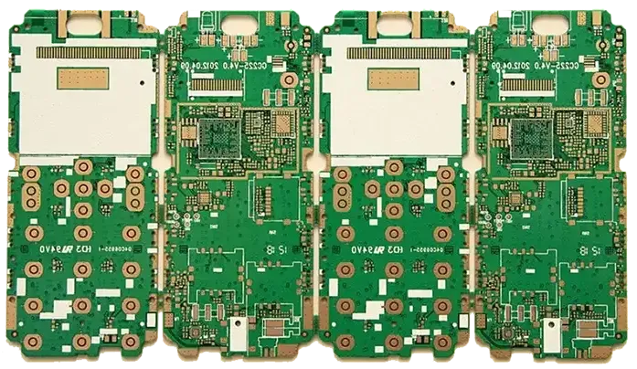
FR4 thin PCB is commonly used in consumer electronics, such as laptops, tablets, and basic IoT devices. Its rigidity makes it suitable for designs where flexibility isn't required, and its affordability supports large-scale production. However, for high-frequency applications above 1 GHz, FR4 may not be the best choice due to its higher dielectric constant and signal loss.
Polyimide Thin PCB: Flexibility and High-Temperature Performance
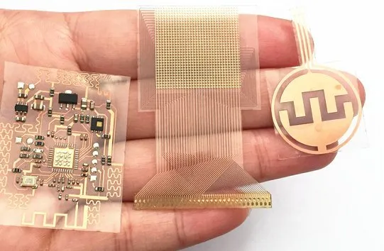
Polyimide thin PCB materials are known for their flexibility and exceptional thermal stability, making them a top choice for flexible and rigid-flex PCB designs. With thicknesses often below 0.3 mm, polyimide substrates are perfect for applications where bending or folding is necessary.
Properties of Polyimide Thin PCB
- Dielectric Constant (Dk): Around 3.4 to 3.5 at 1 MHz, offering better performance than FR4 for moderate-frequency applications.
- Thermal Resistance: Can withstand temperatures up to 260°C or higher, ideal for harsh environments and reflow soldering processes.
- Flexibility: Highly flexible, allowing for dynamic bending without cracking or breaking.
- Cost: More expensive than FR4 due to its advanced properties and manufacturing complexity.
Applications of Polyimide Thin PCB
Polyimide thin PCBs are widely used in wearable technology, medical devices, and aerospace applications. For instance, in a smartwatch, the PCB must conform to the curved shape of the device, making polyimide the ideal substrate. Its ability to handle high temperatures also suits automotive electronics exposed to heat and vibration.
If your design requires a substrate that bends without losing performance, polyimide thin PCB is a strong contender. Its slightly lower dielectric constant compared to FR4 also makes it better for applications up to a few gigahertz.
BT Material Thin PCB: High Performance for Advanced Designs
BT (Bismaleimide Triazine) material thin PCB is a high-performance substrate designed for applications requiring excellent thermal and electrical properties. Often used in advanced electronics, BT materials are available in ultra-thin forms, sometimes as low as 0.1 mm, catering to cutting-edge designs.
Properties of BT Material Thin PCB
- Dielectric Constant (Dk): Typically between 3.0 and 3.5 at 1 MHz, providing better signal integrity than FR4 and comparable to polyimide.
- Thermal Resistance: Exceptional heat resistance, often exceeding 180°C, with some variants handling up to 250°C.
- Mechanical Strength: Offers good rigidity and durability despite its thin profile.
- Cost: Higher than both FR4 and polyimide due to its specialized formulation and performance benefits.
Applications of BT Material Thin PCB
BT material thin PCB is often found in high-frequency and high-speed applications, such as telecommunications equipment, advanced computing systems, and RF modules. For example, in 5G technology, where signal speeds can exceed 10 Gbps, BT substrates help minimize signal loss and maintain performance. Its thermal stability also makes it suitable for environments with fluctuating temperatures.
For engineers working on next-generation electronics, BT material thin PCB offers the precision and reliability needed to push boundaries. However, its higher cost means it's typically reserved for projects where performance outweighs budget concerns.
Dielectric Constant in Thin PCB: Why It Matters
The dielectric constant (Dk) of a thin PCB material directly affects signal speed and integrity, especially in high-frequency designs. A lower Dk means faster signal propagation and less energy loss, which is critical for applications like 5G, automotive radar, and high-speed digital circuits.
Comparing Dielectric Constants
- FR4 Thin PCB: Dk of 4.4-4.8, suitable for low to mid-frequency applications (up to 1 GHz) but less ideal for higher frequencies due to signal delays.
- Polyimide Thin PCB: Dk of 3.4-3.5, offering a middle ground for moderate-frequency designs (up to 5 GHz).
- BT Material Thin PCB: Dk of 3.0-3.5, excellent for high-frequency designs (above 5 GHz) with minimal signal loss.
For instance, in a high-speed design operating at 10 GHz, a material with a Dk of 3.0 can reduce signal delay by approximately 20% compared to a Dk of 4.5. This difference can make or break the performance of your device. When selecting a substrate, always match the dielectric constant to your signal requirements to avoid costly redesigns.
How to Choose the Right Ultra-Thin PCB Material
Selecting the right ultra-thin PCB material depends on your project's specific needs. Here's a step-by-step approach to guide your decision:
- Define Your Application: Are you designing for consumer electronics, medical devices, or high-frequency telecom systems? Each field has unique demands for flexibility, thermal resistance, and signal speed.
- Evaluate Frequency Requirements: For high-frequency designs, prioritize materials with a low dielectric constant like BT or polyimide. For lower frequencies, FR4 thin PCB may suffice.
- Consider Thermal and Mechanical Needs: If your PCB will face high temperatures or needs to bend, opt for polyimide or BT materials. For rigid, standard designs, FR4 is often enough.
- Set a Budget: Balance performance with cost. FR4 thin PCB is the most economical, while BT material thin PCB offers top-tier performance at a premium price.
- Test and Prototype: Work with a trusted PCB manufacturer to create prototypes and test your chosen material under real-world conditions.
By following these steps, you can narrow down your options and select a substrate that aligns with both technical and financial goals.
Challenges and Solutions with Ultra-Thin PCB Materials
While ultra-thin PCB materials offer significant advantages, they come with challenges. Here's how to address common issues:
- Mechanical Fragility: Ultra-thin substrates are more prone to damage during handling or assembly. Solution: Use automated assembly processes and protective coatings to minimize stress.
- Signal Integrity: Thin materials can suffer from crosstalk or impedance mismatches. Solution: Optimize trace layouts and use materials with appropriate dielectric constants for your frequency range.
- Thermal Management: Thin PCBs may struggle to dissipate heat. Solution: Incorporate thermal vias or heat sinks into your design to manage temperature.
Addressing these challenges early in the design phase can save time and resources, ensuring your ultra-thin PCB performs as expected.
Future Trends in Ultra-Thin PCB Materials
The demand for smaller, faster, and more efficient electronics continues to drive innovation in ultra-thin PCB materials. Emerging trends include the development of hybrid substrates that combine the benefits of multiple materials, such as FR4 and polyimide, for enhanced performance. Additionally, advancements in low-loss materials with dielectric constants below 2.5 are paving the way for even higher-frequency applications, supporting technologies like 6G and beyond.
Sustainability is also becoming a focus, with manufacturers exploring eco-friendly substrates that reduce environmental impact without sacrificing quality. Staying updated on these trends can give your designs a competitive edge in the fast-evolving electronics industry.
Conclusion: Make the Right Choice for Your Ultra-Thin PCB Design
Choosing the right ultra-thin PCB material is a critical step in creating reliable, high-performing electronics. Whether you opt for the affordability of FR4 thin PCB, the flexibility of polyimide thin PCB, or the high-frequency capabilities of BT material thin PCB, understanding properties like dielectric constant in thin PCB designs ensures your project succeeds.
By considering your application's needs, frequency requirements, and budget, you can confidently select a substrate that meets your goals. With the insights from this ultimate guide, you're well-equipped to design ultra-thin PCBs that push the boundaries of innovation.


