ALLPCB


If you're looking to design or manufacture a rigid-flex PCB, choosing the right materials, substrates, and adhesives is crucial for performance, durability, and cost-efficiency. This guide dives deep into rigid-flex PCB materials, flexible PCB substrates, polyimide PCB options, adhesive selection for PCB, and rigid-flex PCB stackup strategies to help you make informed decisions. Whether you're an engineer or a product designer, you'll find practical insights and detailed information to ensure your project succeeds.
In the sections below, we'll explore the essential components of rigid-flex PCBs, break down material choices, and provide actionable tips for selecting the best substrates and adhesives for your specific application. Let's get started with everything you need to know to build reliable and high-performing circuit boards.
What Are Rigid-Flex PCBs and Why Do Materials Matter?
Rigid-flex PCBs combine the benefits of rigid and flexible circuit boards into a single design. They consist of rigid sections for mounting components and flexible sections that allow bending or folding, making them ideal for compact electronics like smartphones, medical devices, and aerospace systems. The materials used in these boards directly impact their mechanical strength, thermal stability, electrical performance, and overall lifespan.
Selecting the right rigid-flex PCB materials ensures that your design can withstand environmental stresses, maintain signal integrity, and meet manufacturing requirements. Poor material choices can lead to issues like delamination, cracking, or signal loss, especially in high-frequency or high-temperature applications. With the right substrates and adhesives, you can optimize your design for both performance and cost.
Image Suggestion 1
Location: After the above paragraph.
Description: A diagram showing a cross-section of a rigid-flex PCB with labeled rigid and flexible sections.
Key Materials in Rigid-Flex PCB Design
Rigid-flex PCBs rely on a combination of materials to achieve their unique properties. The primary components include substrates for both rigid and flexible sections, conductive layers, and adhesives to bond them together. Below, we'll break down each category and highlight the most common options used in the industry.
1. Flexible PCB Substrates: The Backbone of Flexibility
The flexible PCB substrate is the foundation of the bendable sections in a rigid-flex design. It needs to be durable, lightweight, and capable of withstanding repeated flexing without breaking. Here are the most popular materials for flexible substrates:
- Polyimide (PI): Known for its excellent thermal stability and flexibility, polyimide PCB materials are the go-to choice for most flexible and rigid-flex designs. Polyimide can handle temperatures up to 260°C, making it suitable for harsh environments. It also offers good chemical resistance and a dielectric constant of around 3.5, which supports reliable signal transmission.
- Polyester (PET): A cost-effective alternative to polyimide, polyester is less common in high-performance rigid-flex PCBs due to its lower thermal resistance (up to 150°C). It's often used in less demanding applications like consumer electronics.
- PTFE (Polytetrafluoroethylene): Used in high-frequency applications, PTFE substrates offer a low dielectric constant (around 2.1) for minimal signal loss. However, they are more expensive and less flexible than polyimide.
For most rigid-flex designs, polyimide strikes the best balance between performance and cost. Its ability to endure bending cycles—often exceeding 100,000 cycles in dynamic applications—makes it a reliable choice for long-term use.
2. Rigid Substrates: Stability for Components
The rigid sections of a rigid-flex PCB provide structural support for mounting components. These sections typically use the same materials as standard rigid PCBs, with the following being the most common:
- FR-4: A glass-reinforced epoxy laminate, FR-4 is widely used due to its affordability and mechanical strength. It has a dielectric constant of about 4.5 and can handle temperatures up to 130°C in standard grades, though high-Tg versions extend this to 170°C or more.
- High-Tg Materials: For applications requiring better thermal performance, high-Tg FR-4 or other specialized laminates are used to prevent warping or degradation at elevated temperatures.
- Ceramic-Filled Materials: In high-frequency or high-power designs, ceramic-filled substrates offer superior thermal conductivity and a lower dielectric constant (around 3.0), reducing signal loss.
Choosing between these rigid materials depends on your project's thermal, mechanical, and electrical requirements. For instance, if your design operates at high frequencies above 1 GHz, ceramic-filled materials may be worth the added cost to maintain signal integrity.
Image Suggestion 2
Location: After the rigid substrates section.
Description: A comparison chart of rigid substrate materials (FR-4, High-Tg, Ceramic-Filled) showing thermal resistance and dielectric constants.
3. Conductive Layers: Ensuring Electrical Performance
Copper is the standard conductive material in rigid-flex PCBs due to its excellent conductivity and affordability. Two types of copper are commonly used in flexible sections:
- Rolled Annealed (RA) Copper: Preferred for flexible layers, RA copper is more ductile and can withstand repeated bending without cracking. It typically comes in thicknesses of 0.5 oz to 2 oz (17-70 μm).
- Electrodeposited (ED) Copper: Often used in rigid sections, ED copper is less flexible but suitable for static areas. It's also available in similar thickness ranges.
The choice of copper type and thickness affects both flexibility and current-carrying capacity. For high-current applications, thicker copper (e.g., 2 oz) is necessary, while thinner copper (e.g., 0.5 oz) is better for tight bends in flexible areas.
Adhesive Selection for PCB: Bonding Layers Effectively
In rigid-flex PCBs, adhesives play a critical role in bonding flexible and rigid layers together. Poor adhesive selection for PCB can lead to delamination, reduced flexibility, or failure under thermal stress. Here are the main types of adhesives used and factors to consider when choosing one:
Types of Adhesives for Rigid-Flex PCBs
- Acrylic Adhesives: These are widely used due to their flexibility and strong bonding capabilities. Acrylic adhesives can handle temperatures up to 150°C and are resistant to moisture and chemicals, making them ideal for most rigid-flex applications.
- Epoxy Adhesives: Known for their high strength and thermal resistance (up to 180°C), epoxy adhesives are used in high-temperature environments. However, they are less flexible than acrylic options and may crack under repeated bending.
- Adhesiveless Laminates: Some modern rigid-flex designs use adhesiveless processes, where flexible substrates like polyimide are directly bonded to rigid layers using heat and pressure. This reduces thickness and improves thermal performance but requires specialized manufacturing capabilities.
Factors to Consider in Adhesive Selection
When selecting an adhesive, consider the following:
- Thermal Resistance: Ensure the adhesive can withstand the operating temperature of your device. For example, if your PCB will experience temperatures above 150°C, epoxy or adhesiveless options are better choices.
- Flexibility: For dynamic flexing applications, prioritize adhesives with high elasticity, like acrylics, to prevent cracking.
- Thickness: Thinner adhesive layers reduce the overall stackup height, which is critical for compact designs. Typical adhesive thicknesses range from 12 to 25 μm.
- Dielectric Properties: Adhesives with a low dielectric constant (around 3.0-3.5) minimize signal interference, especially in high-frequency designs.
Balancing these factors ensures that your adhesive choice supports both mechanical and electrical performance in your rigid-flex PCB.
Image Suggestion 3
Location: After the adhesive selection section.
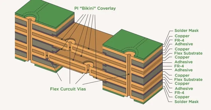
Description: A visual of adhesive layers in a rigid-flex PCB stackup, highlighting bonding between rigid and flexible sections.
Understanding Rigid-Flex PCB Stackup Design
The rigid-flex PCB stackup refers to the arrangement of layers in your circuit board, including rigid substrates, flexible substrates, copper layers, and adhesives. A well-designed stackup ensures signal integrity, mechanical stability, and manufacturability. Here's how to approach stackup design:
Common Stackup Configurations
- 2-Layer Rigid with 1-Layer Flex: A basic configuration for simple designs, with two rigid layers for components and one flexible layer for bending. This is cost-effective but limited in complexity.
- 4-Layer Rigid with 2-Layer Flex: A more common setup for advanced applications, offering additional routing space and flexibility. This stackup might include two rigid sections sandwiching a dual-layer flexible core.
- Multilayer with Embedded Flex: High-end designs may feature multiple rigid and flexible layers, with flex sections embedded within the stackup. This is ideal for compact, high-density electronics.
Layer counts can range from 2 to 20 or more, depending on the complexity of the design. Each additional layer increases manufacturing cost, so balance performance needs with budget constraints.
Stackup Design Tips
- Minimize Transitions: Reduce the number of transitions between rigid and flexible sections to avoid stress points. Each transition should be reinforced with proper adhesive or coverlay materials.
- Signal Integrity: Place high-speed signal traces in inner layers to shield them from interference. Maintain controlled impedance, often targeting 50 ohms for single-ended signals or 100 ohms for differential pairs, by adjusting trace width and dielectric thickness.
- Bend Radius: Design flexible sections with a minimum bend radius of at least 10 times the thickness of the flex layer to prevent cracking. For a 0.1 mm thick flex layer, aim for a bend radius of 1 mm or more.
A carefully planned stackup can prevent issues like signal crosstalk or mechanical failure, ensuring your rigid-flex PCB performs as intended.
Image Suggestion 4
Location: After the stackup design tips.
Description: A detailed diagram of a multilayer rigid-flex PCB stackup with labeled layers and transitions.
How to Choose the Right Materials for Your Rigid-Flex PCB
Selecting the best rigid-flex PCB materials involves evaluating your project's specific needs. Follow these steps to make an informed decision:
- Define Application Requirements: Determine the operating environment, including temperature range, humidity, and mechanical stress. For high-temperature applications (above 150°C), prioritize polyimide substrates and epoxy adhesives.
- Assess Electrical Needs: Identify signal speed and frequency requirements. High-frequency designs (above 1 GHz) benefit from low-dielectric materials like PTFE or ceramic-filled laminates.
- Consider Flexibility: If your design requires dynamic bending, choose flexible substrates like polyimide and RA copper with high bend cycle ratings (e.g., 100,000 cycles or more).
- Balance Cost and Performance: While premium materials improve performance, they increase costs. For budget-sensitive projects, standard FR-4 and acrylic adhesives may suffice for less demanding applications.
- Consult with Manufacturers: Work closely with your PCB fabrication partner to ensure material compatibility with their processes and to validate your stackup design.
By aligning material choices with your project's goals, you can achieve a balance of reliability, performance, and cost-efficiency.
Challenges and Solutions in Rigid-Flex Material Selection
Designing with rigid-flex PCBs comes with unique challenges. Here are some common issues and how to address them:
- Thermal Expansion Mismatch: Different materials expand at different rates under heat, leading to stress or delamination. Solution: Use materials with similar coefficients of thermal expansion (CTE), such as pairing polyimide flex layers with high-Tg rigid substrates (CTE of 12-16 ppm/°C).
- Signal Loss in High-Frequency Designs: High dielectric constants can cause signal degradation. Solution: Opt for low-loss materials with dielectric constants below 3.5 and maintain controlled impedance in your stackup.
- Mechanical Failure at Bend Points: Repeated bending can crack flexible layers or adhesives. Solution: Design with generous bend radii and use highly flexible materials like RA copper and acrylic adhesives.
Proactively addressing these challenges during the design phase can save time and reduce the risk of costly rework.
Conclusion: Building Better Rigid-Flex PCBs with the Right Materials
Choosing the right rigid-flex PCB materials, flexible PCB substrates, and adhesives is a critical step in creating reliable, high-performing circuit boards. From selecting polyimide PCB substrates for flexibility to optimizing adhesive selection for PCB bonding, every decision impacts the final product's quality. A well-designed rigid-flex PCB stackup ties it all together, ensuring mechanical stability and electrical performance.
At ALLPCB, we're committed to helping you navigate these choices with expert guidance and high-quality manufacturing solutions. Whether you're working on a compact consumer device or a complex aerospace system, understanding your material options empowers you to build better products. Use the insights from this guide to refine your designs and achieve success in your next rigid-flex PCB project.
Image Suggestion 5
Location: Before the conclusion.
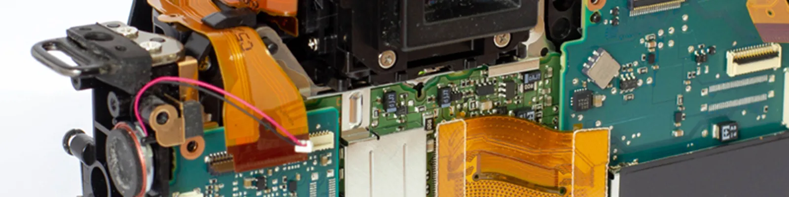
Description: A photo of a finished rigid-flex PCB in a real-world application, such as a folded design in a compact electronic device.