 ALLPCB


In the fast-evolving world of autonomous vehicles, the reliability of control systems is critical. At the heart of these systems are Printed Circuit Boards (PCBs) that manage everything from sensor data processing to vehicle navigation. Ensuring these PCBs can withstand harsh automotive environments is non-negotiable. This blog post dives deep into the importance of reliability testing and validation for autonomous vehicle control PCBs, exploring key methods like automotive PCB testing standards, accelerated life testing, vibration testing, thermal shock testing, and HALT/HASS testing. Whether you're an engineer or a manufacturer, you'll find actionable insights to ensure your PCBs meet the highest standards of durability and performance.
Why Reliability Testing Matters for Autonomous Vehicle PCBs
Autonomous vehicles operate in unpredictable conditions, from extreme temperatures to constant vibrations on rough roads. A single failure in the control PCB can lead to catastrophic consequences, compromising safety and functionality. Reliability testing ensures that these critical components can endure real-world stresses over their expected lifespan, often 10-15 years in automotive applications. By adhering to strict automotive PCB testing standards, manufacturers can prevent costly recalls, maintain user trust, and comply with industry regulations like ISO 26262 for functional safety.
In the sections below, we’ll break down the specific testing methods used to validate PCB reliability, providing detailed explanations and practical examples to guide your approach.
Understanding Automotive PCB Testing Standards
Automotive PCB testing standards are the foundation of reliability validation. These standards, often set by organizations like the International Organization for Standardization (ISO) and the Automotive Electronics Council (AEC), provide guidelines for designing and testing PCBs to ensure they meet the rigorous demands of vehicle environments. One key standard, AEC-Q100, focuses on integrated circuits and outlines stress tests for temperature, humidity, and electrical performance. For PCBs specifically, standards like IPC-A-600 and IPC-A-610 define acceptability criteria for bare boards and assemblies, ensuring consistent quality.
For autonomous vehicle control PCBs, compliance with these standards is essential. For instance, a PCB controlling a vehicle's LiDAR system must maintain signal integrity at high frequencies (often above 1 GHz) under temperature swings from -40°C to 85°C. Testing against automotive PCB testing standards verifies that the board’s materials, traces, and components can handle such conditions without degradation. This often involves evaluating dielectric constants (typically around 3.5-4.5 for FR-4 materials) and ensuring impedance values stay within tight tolerances, such as ±10% of 50 ohms for high-speed signals.
Accelerated Life Testing for PCBs: Simulating Years in Days
Accelerated Life Testing (ALT) for PCBs is a method used to simulate the long-term effects of environmental stress in a compressed timeframe. This is especially important for autonomous vehicle control PCBs, where a 15-year lifespan must be validated in mere weeks or months. ALT subjects PCBs to elevated stress conditions—such as high temperatures, humidity, and voltage—to identify potential failure points like solder joint cracks or component degradation.
A typical ALT setup might expose a PCB to 125°C (well above the standard operating range of 85°C) and 85% relative humidity for 1,000 hours. This test can simulate 10 years of normal use, based on models like the Arrhenius equation, which correlates temperature with aging rates. For example, a power management PCB in an autonomous vehicle might be tested to ensure its capacitors maintain a capacitance tolerance of ±10% after ALT, preventing voltage fluctuations that could disrupt control systems.
By using accelerated life testing for PCBs, manufacturers can predict failure rates and improve designs before mass production. This proactive approach reduces the risk of field failures, especially in critical systems like braking or steering control.
Vibration Testing for PCBs: Enduring the Road’s Rigors
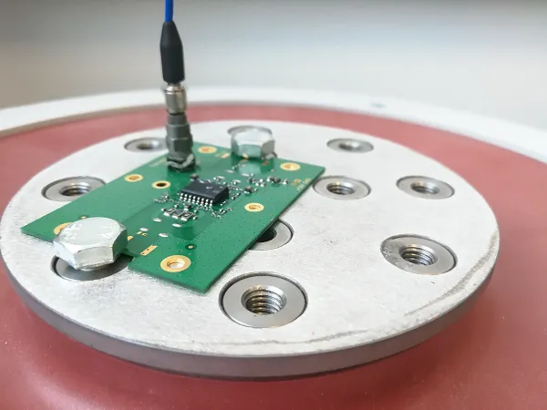
Vibration testing for PCBs is crucial in the automotive sector, where constant motion and road irregularities create mechanical stress. Autonomous vehicle control PCBs, often mounted in exposed areas like under the chassis, must withstand vibrations ranging from 5 Hz to 2,000 Hz with accelerations up to 20 G (gravitational force). Failure to endure these conditions can lead to cracked solder joints, broken traces, or dislodged components, disrupting critical functions like sensor data processing.
During vibration testing, PCBs are mounted on shaker tables that replicate real-world conditions. Tests often follow standards like MIL-STD-810 or ISO 16750-3, which define profiles for random and sinusoidal vibrations. For instance, a PCB controlling an autonomous vehicle’s camera system might be tested at 10 G for 8 hours across a frequency sweep to ensure no resonance points cause mechanical failure. Engineers analyze results using tools like strain gauges to measure stress on specific board areas, ensuring design robustness.
Vibration testing for PCBs helps identify weak points, allowing for design adjustments such as adding conformal coatings (to dampen vibrations) or reinforcing mounting points. This ensures long-term reliability on the road.
Thermal Shock Testing for PCBs: Surviving Temperature Extremes
Thermal shock testing for PCBs evaluates a board’s ability to handle rapid temperature changes, a common scenario in automotive environments. Autonomous vehicles may encounter shifts from freezing winters (-40°C) to scorching summers (85°C) within hours, especially in regions with extreme climates. Such changes can cause thermal expansion mismatches between materials, leading to cracked solder joints or delaminated layers.
In a typical thermal shock test, a PCB is cycled between two chambers—one at -55°C and another at 125°C—with a transition time of less than 10 seconds. Standards like IPC-TM-650 outline cycles (often 100-500) to stress the board. For example, a control PCB for an autonomous vehicle’s battery management system might undergo 200 cycles to ensure its multilayer structure (with a typical coefficient of thermal expansion of 14-18 ppm/°C for FR-4) doesn’t warp or crack, maintaining electrical continuity for power delivery.
Thermal shock testing for PCBs is vital for validating material choices and assembly processes, ensuring that autonomous vehicle systems remain operational regardless of environmental swings.
HALT and HASS Testing: Pushing PCBs to Their Limits
Highly Accelerated Life Testing (HALT) and Highly Accelerated Stress Screening (HASS) are advanced methods to uncover design weaknesses and ensure manufacturing consistency for autonomous vehicle control PCBs. These tests go beyond standard protocols by pushing boards to failure, revealing vulnerabilities that might not surface in conventional testing.
HALT involves subjecting a PCB to extreme conditions—combining temperature (from -100°C to 200°C), vibration (up to 50 G), and rapid thermal transitions—to identify the operational and destruct limits. For instance, a PCB for an autonomous vehicle’s navigation system might fail at 180°C due to component breakdown, prompting a redesign with higher-rated parts. HALT is typically performed during the design phase to improve robustness.
HASS, on the other hand, is a production-level test using slightly less extreme conditions (based on HALT findings) to screen out defective units. A batch of PCBs might be tested at 120°C and 20 G vibration for 30 minutes to catch assembly flaws like poor soldering, ensuring only reliable boards reach the market.
HALT/HASS testing is invaluable for autonomous vehicle PCBs, where safety and reliability are paramount. These methods help manufacturers achieve near-zero failure rates, even in high-stakes applications.
Key Challenges in Testing Autonomous Vehicle Control PCBs
Testing autonomous vehicle control PCBs comes with unique challenges. First, the complexity of these boards—often featuring high-density interconnects (HDI) with trace widths below 3 mils and multiple layers—makes failure analysis difficult. A single micro-crack can disrupt a critical signal path, yet remain undetected without advanced X-ray inspection.
Second, the integration of diverse components (sensors, microcontrollers, RF modules) means each part has different stress tolerances. A capacitor rated for 105°C might fail long before a resistor rated for 150°C, creating weak links in the system. Testing must account for these disparities to ensure overall reliability.
Finally, time and cost constraints often pressure manufacturers to shorten testing cycles. However, cutting corners on methods like accelerated life testing for PCBs or vibration testing can lead to undetected flaws, risking safety in autonomous vehicles. Balancing thoroughness with efficiency is key.
Best Practices for Reliable PCB Design and Testing
To achieve reliable autonomous vehicle control PCBs, consider these best practices during design and testing:
- Material Selection: Use high-Tg (glass transition temperature) materials like FR-4 with Tg above 170°C to handle thermal stress. For high-frequency signals, consider low-loss laminates with dielectric constants below 3.0.
- Robust Assembly: Ensure proper solder paste application and reflow profiles to avoid weak joints. Use automated optical inspection (AOI) to detect assembly defects early.
- Comprehensive Testing: Combine multiple methods—vibration testing, thermal shock testing, and HALT/HASS testing—to cover all stress factors. Follow automotive PCB testing standards for consistency.
- Simulation Tools: Use software to simulate thermal and mechanical stress before physical testing. This can predict failure points, like excessive strain on a 0.5 mm BGA pitch, saving time and resources.
- Iterative Improvement: Analyze test data to refine designs. If a PCB fails thermal shock testing after 100 cycles, adjust layer stack-up or component placement to enhance durability.
By following these practices, manufacturers can build PCBs that meet the stringent demands of autonomous vehicle applications.
Conclusion: Ensuring Safety Through Rigorous PCB Testing
Reliability testing and validation of autonomous vehicle control PCBs are not just technical necessities—they are the backbone of safe, dependable self-driving technology. From adhering to automotive PCB testing standards to implementing accelerated life testing, vibration testing, thermal shock testing, and HALT/HASS testing, each method plays a vital role in ensuring these critical components perform flawlessly under stress. As the autonomous vehicle industry grows, so does the need for robust testing protocols that keep pace with innovation.
At ALLPCB, we understand the importance of delivering high-quality, reliable PCBs for automotive applications. Our commitment to rigorous testing and validation ensures that your control systems operate without fail, even in the harshest conditions. By prioritizing reliability, we help pave the way for safer, smarter vehicles on the road.


