 ALLPCB


Flexible printed circuit boards (PCBs) have transformed modern electronics, enabling compact, lightweight, and adaptable designs in everything from smartphones to aerospace systems. However, their inherent flexibility can sometimes be a drawback—especially in areas requiring stability, such as component mounting zones or connector interfaces. This is where PCB stiffeners come into play. These unsung heroes provide mechanical reinforcement, ensuring flexible circuits remain durable and reliable under stress. In this blog, we'll dive into the world of PCB stiffeners, exploring their purpose, types, materials, and design considerations to help engineers optimize their flexible circuit designs.
What Are PCB Stiffeners and Why Do They Matter?
PCB stiffeners are rigid or semi-rigid materials added to specific areas of a flexible circuit to enhance mechanical strength and stability. Unlike the core electrical components of a PCB, stiffeners don't contribute to the circuit's functionality—they're purely mechanical. Their primary role is to prevent excessive bending, support heavy components, and maintain structural integrity during assembly and operation.
Why do they matter? Flexible PCBs, by design, can bend up to 360 degrees and endure millions of flex cycles. While this adaptability is a strength, it can lead to issues like cracked solder joints, trace damage, or component detachment in high-stress areas. For example, a flexible PCB in a wearable device might need to flex around a wrist but remain rigid near a surface-mount connector. Without stiffeners, the repeated bending could compromise the connection, leading to failure rates as high as 30% in dynamic applications, according to industry studies. Stiffeners address these challenges, making them essential for enhancing durability and reliability.
Key Functions of PCB Stiffeners in Flexible Circuits
Stiffeners serve multiple purposes in flexible circuit designs, each tailored to specific engineering needs. Here's a breakdown of their key functions:
1. Mechanical Support for Components
Heavy components, such as connectors or surface-mount devices (SMDs), exert stress on flexible substrates. Stiffeners provide a rigid platform, preventing the flex material from deforming under weight. For instance, a 0.5 oz copper trace on a 25 µm polyimide substrate can withstand only about 10 grams of force before bending—far less than the 50-100 grams typical connectors impose.
2. Flexural Resistance
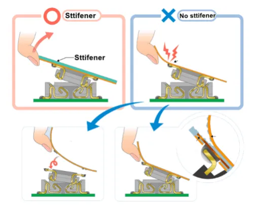
In areas where bending must be controlled, stiffeners limit flexing to protect delicate traces and solder joints. This is critical in applications like foldable displays, where bending radii as tight as 1 mm are common, yet certain zones must remain flat.
3. Enhanced Assembly Precision
During automated assembly processes like pick-and-place or reflow soldering, a flat surface is crucial. Stiffeners ensure proper alignment and stability, reducing errors. Without them, misalignment rates can increase by up to 15%, per manufacturing data.
4. Vibration and Shock Mitigation
In automotive or industrial applications, PCBs face constant vibration. Stiffeners dampen resonance, improving signal integrity and reducing fatigue failure. Tests show stiffened flex circuits can endure 20% more vibration cycles (e.g., 10,000 vs. 8,000 at 20 Hz) before trace cracking occurs.
5. Meeting Connector Specifications
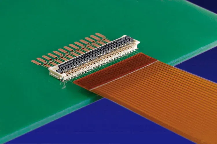
Zero Insertion Force (ZIF) connectors, common in flex designs, require precise thicknesses—typically 0.2 mm or 0.3 mm with tolerances of ±0.03 mm. Stiffeners build up these areas to meet specs without sacrificing overall flexibility.
These functions highlight why stiffeners are indispensable for engineers balancing flexibility with durability.
Types of PCB Stiffeners: Tailoring to Your Design
Not all stiffeners are created equal. Depending on the application, engineers can choose from several types, each with unique benefits. Here's a look at the most common options:
1. Full Board Stiffeners
These cover the entire PCB, offering maximum support. They're ideal for designs needing uniform rigidity but add weight and cost—up to 20% more than partial stiffeners, based on material usage.
2. Partial Stiffeners
Applied to specific zones (e.g., under components), partial stiffeners balance flexibility and support. They're cost-effective and common in consumer electronics, where only 10-30% of the board typically needs reinforcement.
3. Edge Stiffeners
Reinforcing PCB edges, these prevent bending during handling or assembly. They're often used in array configurations, reducing edge stress by up to 25% in testing.
4. Localized Stiffeners
Small, targeted stiffeners support individual components or high-stress points. For example, a 5 mm x 5 mm stiffener under an SMD pad can increase solder joint lifespan by 50% in flex zones.
Materials for PCB Stiffeners: Properties and Trade-offs
The choice of stiffener material significantly impacts performance, cost, and manufacturability. Here's a detailed look at the most popular options:
1. FR4 (Fiberglass Reinforced Epoxy)
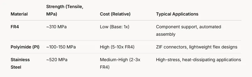
- Properties: High mechanical strength (tensile strength ~310 MPa), cost-effective, solderable.
- Thickness Range: 0.2 mm to 1.5 mm.
- Pros: Widely available, compatible with PCB processes, supports plated through-holes (PTH).
- Cons: Less flexible, heavier (density ~1.85 g/cm³).
- Use Case: Component support in automated assembly, e.g., a 0.8 mm FR4 stiffener under a 2-gram connector.
2. Polyimide (PI, e.g., Kapton)
- Properties: Lightweight (density ~1.42 g/cm³), thermally stable (up to 400°C), flexible.
- Thickness Range: 25 µm to 150 µm.
- Pros: Ideal for ZIF connectors, high bond strength with thermal adhesives.
- Cons: Higher cost (5-10x FR4), non-solderable without metallization.
- Use Case: Gold finger reinforcement in wearables, meeting 0.3 mm ZIF specs.
3. Stainless Steel or Aluminum
- Properties: Exceptional rigidity (stainless steel tensile strength ~520 MPa), corrosion-resistant, thermally conductive (aluminum ~200 W/m·K).
- Thickness Range: 0.1 mm to 0.5 mm.
- Pros: Best for high-stress or heat-dissipating applications.
- Cons: Expensive (2-3x FR4), requires custom machining.
- Use Case: Automotive sensors enduring 50°C to 150°C cycles.
4. Plastic (e.g., PET)
- Properties: Lightweight, moldable, moderate strength.
- Thickness Range: 0.1 mm to 0.5 mm.
- Pros: Customizable shapes, low cost.
- Cons: Limited thermal and mechanical performance.
- Use Case: Low-stress reinforcement in budget designs.
Choosing the right material depends on factors like environmental conditions, component weight, and budget. For instance, a polyimide stiffener might cost $0.50 more per unit than FR4 but save $2 in assembly rework due to better ZIF compatibility.
Design Considerations for Effective Stiffener Integration
Integrating stiffeners requires careful planning to maximize their benefits. Here are key considerations for engineers:
1. Placement and Coverage
Place stiffeners where stress is highest—under components, near connectors, or at flex-rigid transitions. Overlap stiffeners with coverlay by at least 0.76 mm (30 mils) to avoid stress points, per IPC-2223 guidelines.
2. Thickness Selection
Match thickness to application needs. A 0.2 mm polyimide stiffener suffices for ZIF connectors, while a 1 mm FR4 stiffener supports a 5-gram component. Exceeding minimum bend radius (e.g., 6x substrate thickness) prevents cracking.
3. Thermal Expansion
Materials like aluminum (CTE ~23 ppm/°C) differ from polyimide (CTE ~20 ppm/°C) or FR4 (CTE ~14 ppm/°C). Mismatched coefficients can cause warping during thermal cycling—up to 0.1 mm deflection in a 50 mm board at 100°C.
4. Manufacturing Compatibility
Ensure stiffener design aligns with assembly processes. FR4 stiffeners with PTH require access holes 0.3 mm larger than solder pads to avoid misalignment, adding 5-10% to fabrication time.
5. Cost vs. Performance
Full board stiffeners might increase material costs by 15-20%, while localized stiffeners keep expenses down. Balance durability needs with budget constraints.
Applications of PCB Stiffeners in Real-World Designs
Stiffeners shine in diverse industries where flexibility and durability must coexist:
- Consumer Electronics: In smartphones, polyimide stiffeners reinforce flex tails to displays, enduring 500,000+ flex cycles.
- Automotive: Stainless steel stiffeners support sensor circuits, resisting vibrations up to 30 G in engine compartments.
- Medical Devices: FR4 stiffeners stabilize pacemaker flex circuits, ensuring reliability over 10-year lifespans.
- Aerospace: Aluminum stiffeners dissipate heat in satellite flex boards, managing 50 W loads in vacuum conditions.
These examples show how stiffeners adapt to specific challenges, enhancing performance where it counts.
How ALLPCB Supports Stiffener-Enhanced Flex Designs
For engineers tackling flexible circuit projects, partnering with a reliable manufacturer is key. ALLPCB offers advanced manufacturing capabilities that streamline stiffener integration. Our quick-turn prototyping delivers flex PCBs with precise stiffener placement, while global logistics ensure fast delivery to keep projects on track.
Conclusion: Strengthening the Future of Flexible Circuits
PCB stiffeners are more than just add-ons—they're critical enablers of durable, reliable flexible circuit designs. By providing mechanical support, controlling flex, and enhancing assembly, they bridge the gap between flexibility and stability. Whether you're designing a compact wearable or a rugged automotive system, understanding stiffener types, materials, and placement can elevate your project's success. As technology pushes for smaller, tougher electronics, stiffeners will remain a cornerstone of innovation, ensuring your designs stand the test of time.
Ready to reinforce your next flexible PCB? Dive into the details, choose the right stiffener, and watch your design's durability soar.


