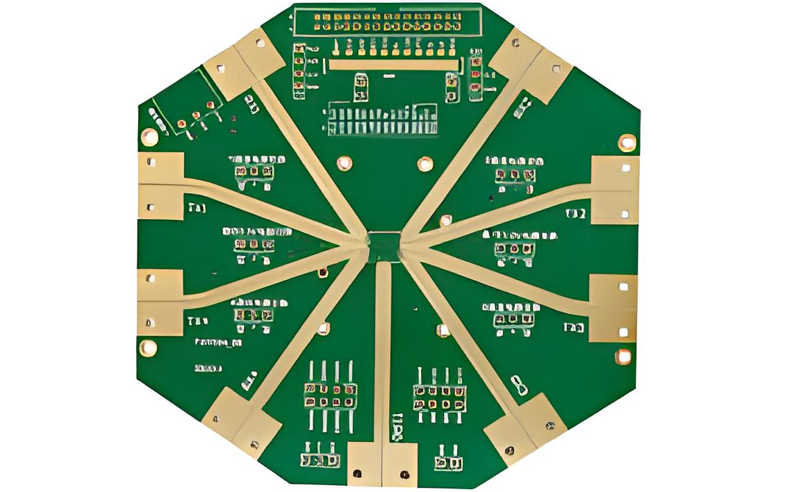
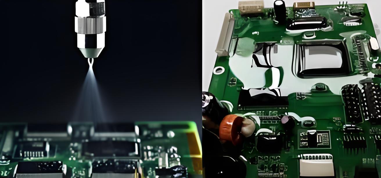
In the high-stakes world of military and aerospace applications, PCB (Printed Circuit Board) design must prioritize redundancy and safety to ensure reliability under extreme conditions. These industries demand PCBs that can withstand harsh environments, maintain functionality during critical missions, and adhere to strict standards. This blog dives deep into the essentials of designing PCBs for military and aerospace use, focusing on built-in redundancy, safety measures, and key considerations like high-temperature laminates, protective coatings, current capacity, and aspect ratio. Whether you're an engineer or a project manager, you'll find actionable insights to create robust and dependable designs.
Why Redundancy and Safety Matter in Military and Aerospace PCB Design
Military and aerospace systems operate in environments where failure is not an option. From satellites enduring the vacuum of space to fighter jets facing intense vibrations and temperature swings, PCBs must perform flawlessly. Redundancy ensures that if one component or system fails, a backup is ready to take over. Safety, on the other hand, involves designing boards that resist environmental hazards and prevent catastrophic failures. Together, these principles form the backbone of reliable PCB design for these critical applications.

Key Military PCB Design Standards to Follow
Military PCB design standards are non-negotiable to ensure durability and performance. These standards provide guidelines for everything from material selection to testing protocols. One of the most critical frameworks is MIL-PRF-31032, which outlines performance requirements for military-grade PCBs. It specifies testing for thermal shock, vibration resistance, and moisture exposure—conditions common in military operations.
Another important standard is IPC-6012, which includes a Class 3 designation for high-reliability electronics often used in military applications. Class 3 requires tighter tolerances, such as a minimum annular ring of 0.002 inches (0.05 mm) for drilled holes, ensuring stronger connections under stress. Adhering to these standards not only guarantees compliance but also builds trust in the PCB's ability to perform in the field.
Beyond formal standards, military designs often incorporate redundancy at the circuit level. For instance, dual power supply paths can be integrated so that if one path fails, the other maintains operation. This approach is vital for mission-critical systems like communication devices or navigation equipment.
Aerospace PCB Design Tips for Optimal Performance
Designing PCBs for aerospace applications requires a unique set of considerations due to the extreme conditions of space and high-altitude flight. Here are some actionable aerospace PCB design tips to ensure reliability and safety:
- Minimize Signal Interference: Use proper grounding and shielding techniques to prevent electromagnetic interference (EMI). For example, maintain a ground plane clearance of at least 0.01 inches (0.25 mm) from signal traces to reduce noise in high-frequency circuits.
- Optimize Thermal Management: Aerospace PCBs often face temperature swings from -55°C to 125°C. Design with thermal vias and heat sinks to dissipate heat, ensuring components stay within operational limits.
- Focus on Component Placement: Place critical components away from board edges to minimize damage from vibrations. Secure heavy components with additional mounting hardware to withstand launch forces of up to 10G or more.
- Incorporate Redundancy: Design duplicate circuits for critical functions like power management or data transmission. This ensures that a single point of failure doesn’t compromise the entire system.

Choosing Aerospace PCB High-Temperature Laminates
Material selection is a cornerstone of aerospace PCB design, especially when it comes to handling extreme temperatures. Aerospace PCB high-temperature laminates are engineered to resist thermal degradation, maintaining structural integrity and electrical performance. Common materials include polyimide and high-Tg (glass transition temperature) FR-4 laminates, which can operate reliably at temperatures above 150°C.
Polyimide laminates, for instance, have a Tg of around 250°C and offer excellent thermal stability, making them ideal for space applications where boards may be exposed to solar radiation. High-Tg FR-4, with a Tg of 170-180°C, is a more cost-effective option for less extreme conditions but still provides better heat resistance than standard FR-4 (Tg of 130°C).
When selecting laminates, consider the coefficient of thermal expansion (CTE). A CTE mismatch between the laminate and components can lead to stress and cracking during temperature cycles. Aim for a CTE close to 14-17 ppm/°C for compatibility with most components. Additionally, ensure the laminate meets outgassing standards like NASA's ASTM E595 to prevent contamination in vacuum environments.
Importance of Aerospace PCB Protective Coatings
Aerospace PCB protective coatings, often referred to as conformal coatings, are essential for safeguarding boards against environmental hazards like moisture, dust, and chemical exposure. These coatings act as a barrier, preventing corrosion and short circuits that could lead to system failure.
Common types of conformal coatings include silicone, acrylic, and urethane. Silicone coatings are particularly suited for aerospace applications due to their wide temperature range (-65°C to 200°C) and flexibility, which helps absorb vibrations. Acrylic coatings, while less flexible, are easier to apply and repair, making them suitable for less demanding environments.
For military and aerospace use, coatings must also resist outgassing in vacuum conditions and meet standards like MIL-I-46058C. Apply coatings with a uniform thickness of 0.002 to 0.005 inches (0.05 to 0.13 mm) to ensure full coverage without interfering with component functionality. Proper application techniques, such as spray or dip coating, are critical to avoid bubbles or uneven layers that could compromise protection.

Calculating Aerospace PCB Current Capacity for Safety
Determining aerospace PCB current capacity is a critical safety factor to prevent overheating and electrical failures. Current capacity depends on trace width, thickness, and the material’s ability to handle heat dissipation. Overloading a trace can lead to thermal runaway, where excessive heat causes further resistance increase, potentially melting the board or starting a fire.
The IPC-2221 standard provides guidelines for calculating current capacity. For a copper trace with a thickness of 1 oz/ft2 (35 μm), a width of 0.01 inches (0.25 mm) can safely carry about 0.5 amps at a temperature rise of 10°C. For higher currents, increase the trace width or use heavier copper (e.g., 2 oz/ft2 or 70 μm) to reduce resistance. For example, a 2 oz/ft2 trace at 0.02 inches (0.5 mm) width can handle approximately 1.5 amps under the same conditions.
In aerospace applications, it's wise to design with a safety margin of at least 20-30% above the expected current to account for unexpected surges or environmental factors. Use simulation tools to model current flow and heat distribution, ensuring traces remain within safe operating limits even under peak loads.
Understanding Aerospace PCB Aspect Ratio for Reliability
The aerospace PCB aspect ratio, defined as the ratio of a via's depth to its diameter, plays a significant role in manufacturing reliability and signal integrity. A high aspect ratio (e.g., 10:1 or higher) means a deep via with a narrow diameter, which can be challenging to plate uniformly and may lead to weak connections or voids in the copper plating.
For aerospace designs, aim for an aspect ratio of 6:1 or lower to ensure manufacturability and reliability. For example, a board with a thickness of 0.062 inches (1.57 mm) should have vias with a diameter of at least 0.01 inches (0.25 mm) to maintain a 6:1 ratio. This ensures proper plating and reduces the risk of failures during thermal cycling or vibration, common in aerospace environments.
High aspect ratios can also affect signal integrity in high-speed circuits by increasing inductance and capacitance. If a higher ratio is unavoidable, consider back-drilling to remove unused via stubs or using microvias, which offer smaller diameters and better performance in dense designs.
Implementing Redundancy in PCB Design for Mission-Critical Systems
Redundancy is a fundamental principle in military and aerospace PCB design to ensure continuous operation even if a component fails. This can be achieved at multiple levels, including hardware, software, and system architecture.
At the hardware level, duplicate critical components like power regulators or microcontrollers. For instance, use two independent voltage regulators feeding the same circuit through diodes, so if one fails, the other takes over without interruption. At the system level, design failover mechanisms, such as secondary communication channels that activate if the primary channel is disrupted.
Redundancy must be balanced with size, weight, and power (SWaP) constraints, especially in aerospace where every gram matters. Use modular designs where redundant systems can be isolated and activated only when needed, minimizing resource use while maintaining safety.
Testing and Validation for Military and Aerospace PCBs
Thorough testing is essential to validate the safety and redundancy of military and aerospace PCBs. Environmental stress testing, such as thermal cycling between -55°C and 125°C, simulates the extreme conditions boards will face. Vibration testing, often conducted at frequencies up to 2000 Hz and amplitudes mimicking launch conditions, ensures mechanical integrity.
Electrical testing, including in-circuit testing (ICT) and functional testing, verifies that redundant systems operate as intended. For example, simulate a power supply failure to confirm that the backup system activates within milliseconds. Additionally, adhere to standards like MIL-STD-810 for environmental testing and MIL-STD-461 for EMI compatibility to meet regulatory requirements.
Conclusion: Building Trust Through Redundancy and Safety
Designing PCBs for military and aerospace applications is a complex but rewarding challenge. By focusing on built-in redundancy and safety, engineers can create boards that perform reliably in the harshest conditions. From adhering to strict military PCB design standards to selecting aerospace PCB high-temperature laminates and protective coatings, every decision impacts the final product’s success. Pay close attention to details like aerospace PCB current capacity and aspect ratio to ensure both functionality and manufacturability.
With these aerospace PCB design tips, you're equipped to tackle the unique demands of these industries. Prioritize robust materials, thoughtful layouts, and rigorous testing to deliver solutions that meet the highest standards of performance and safety. Trust in your design process, and you'll build systems that stand up to the toughest missions.
 ALLPCB


