ALLPCB


Reverse engineering an Engine Control Unit (ECU) PCB can seem like a daunting task, but with the right approach, tools, and patience, it’s entirely achievable. Whether you're an automotive engineer, a hobbyist, or a professional looking to understand the intricacies of an ECU for repair, modification, or research, this guide will walk you through the process step by step. In this blog, we’ll cover everything from analyzing ECU PCB schematics to understanding ECU PCB layout and identifying components, ensuring you have a clear path to success in automotive PCB reverse engineering.
What Is Reverse Engineering an ECU PCB?
Reverse engineering an ECU PCB involves deconstructing and analyzing the printed circuit board of an engine control unit to understand its design, functionality, and interconnections without access to the original schematics or documentation. The goal is often to recreate the schematic, identify components, or modify the board for specific purposes like tuning or repairing a vehicle’s electronic system. This process requires a mix of technical skills, specialized tools, and a methodical approach to uncover the secrets of the board’s design.
In the following sections, we’ll dive deep into the steps and techniques for reverse engineering ECU PCBs, focusing on practical tips for analyzing schematics, understanding layouts, and identifying components. Let’s get started with the fundamentals.
Why Reverse Engineer an ECU PCB?
Before we jump into the how-to, it’s important to understand the reasons behind reverse engineering an ECU PCB. Automotive enthusiasts and professionals often undertake this process for several purposes:
- Repairing Legacy Systems: Many older vehicles rely on ECUs that are no longer manufactured, and original documentation may be unavailable. Reverse engineering helps in repairing or replacing faulty components.
- Performance Tuning: Modifying an ECU to optimize engine performance, fuel efficiency, or emissions often requires understanding the PCB’s design to alter specific circuits or firmware.
- Research and Development: Engineers may analyze competitor designs or legacy systems to learn from them and develop improved solutions.
- Cost-Effective Solutions: Recreating or repairing an ECU can be more affordable than sourcing a rare or expensive replacement unit.
With these motivations in mind, let’s explore the detailed steps to reverse engineer an ECU PCB effectively.
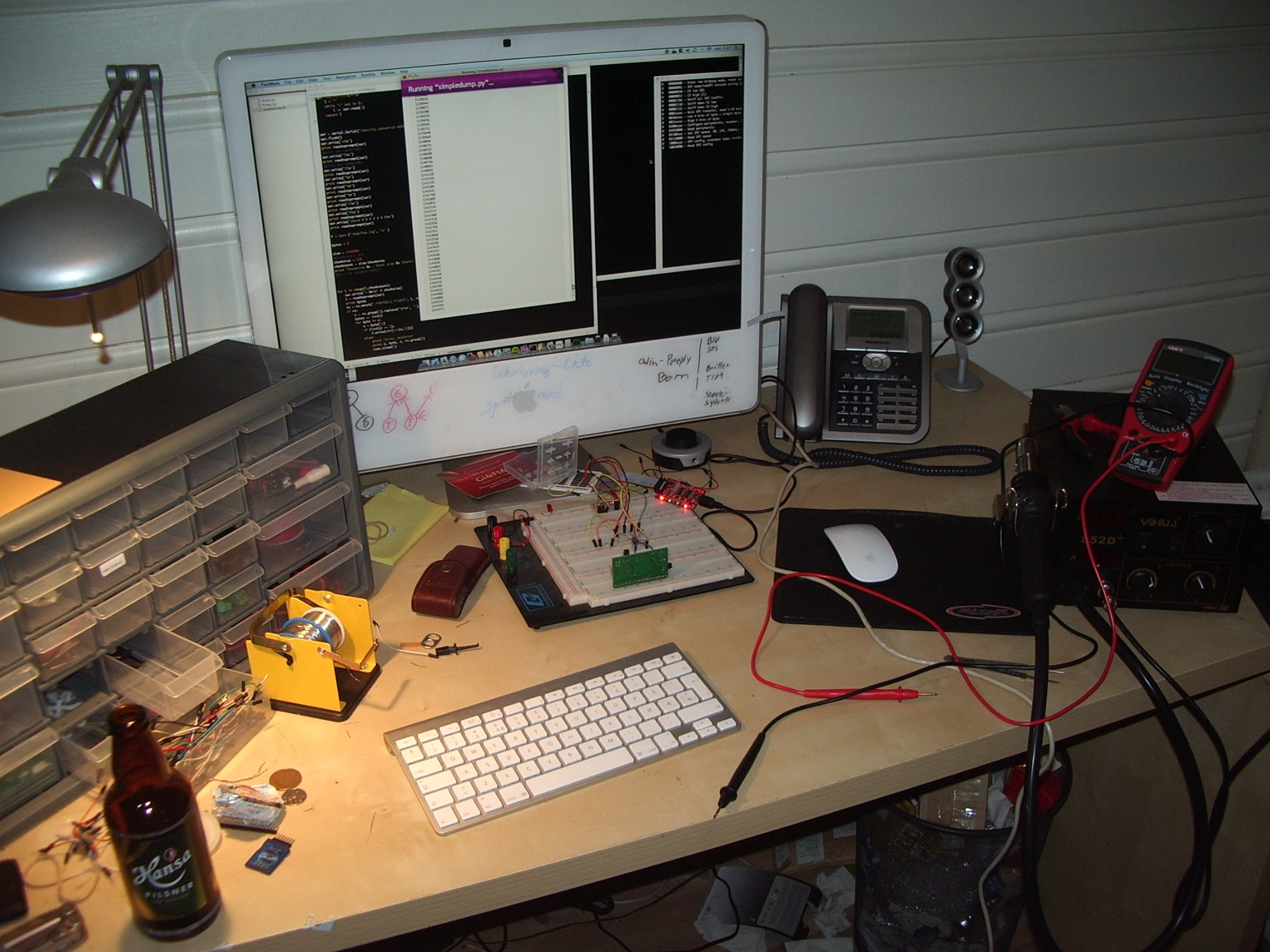
Step 1: Gather the Necessary Tools and Equipment
Reverse engineering an ECU PCB requires a set of specialized tools to inspect, document, and analyze the board. Here’s a list of essentials:
- Multimeter: For measuring voltages, continuity, and resistance across traces and components (e.g., checking a resistor’s value or a capacitor’s integrity).
- Magnifying Glass or Microscope: To inspect tiny components and traces on the PCB, especially in densely packed areas.
- Digital Camera or Smartphone: For capturing high-resolution images of the PCB for documentation and reference.
- Soldering and Desoldering Tools: To remove components if needed for closer inspection or testing.
- Schematic Drawing Software: To recreate the circuit diagram as you uncover connections and components.
- Oscilloscope: Useful for analyzing signal behavior on the board, such as clock signals or data lines (e.g., observing a 5V signal at 1MHz frequency).
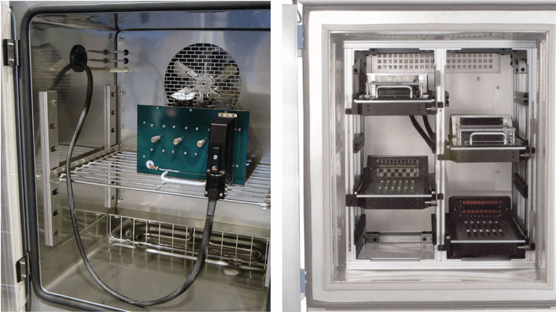
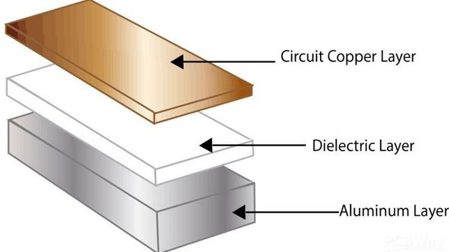
- X-Ray Imaging (Optional): For multi-layer PCBs, X-ray equipment can reveal internal traces and vias that are not visible on the surface.
Step 2: Safety First – Prepare the ECU PCB for Analysis
Working with an ECU PCB involves handling sensitive electronics, so safety is paramount. Follow these precautions before starting:
- Disconnect the ECU from any power source or vehicle battery to avoid short circuits or damage.
- Work in a static-free environment by using an anti-static wrist strap and mat to prevent electrostatic discharge (ESD) from damaging sensitive components.
- Handle the PCB carefully to avoid breaking delicate traces or components.
Once safety measures are in place, remove the ECU from its housing if necessary. Most ECUs are encased in protective metal or plastic enclosures. Use a screwdriver to open the case and expose the PCB for analysis.
Step 3: Document the ECU PCB Thoroughly
Documentation is a critical step in reverse engineering. Before touching any components or traces, take detailed photographs of both sides of the PCB. Focus on:
- Component labels and markings (e.g., part numbers on ICs or resistors).
- Trace patterns and solder points.
- Any visible damage or modifications.
Label each component in your photos or create a reference diagram. This will help when analyzing ECU PCB schematics later. If the PCB is multi-layered, note any visible vias (small holes connecting layers) as they indicate connections between layers.
Step 4: Understanding ECU PCB Layout
Understanding the ECU PCB layout is a foundational step in reverse engineering. The layout refers to the physical arrangement of components and traces on the board. Here’s how to approach it:
- Identify Major Sections: Most ECU PCBs are divided into functional blocks such as power supply, microcontroller, input/output interfaces, and sensor signal processing. Look for larger ICs (integrated circuits) which often indicate the microcontroller or main processor.
- Trace Power Lines: Power traces are usually thicker and connect to components like voltage regulators or capacitors. Use a multimeter to identify power rails (e.g., 5V or 12V lines).
- Locate Ground Planes: Ground planes are large copper areas often covering significant portions of the PCB. They are essential for noise reduction and signal stability.
- Analyze Signal Paths: Thinner traces typically carry signals between components. Follow these traces to understand how data flows between the microcontroller, sensors, and actuators.
By mapping out the layout, you create a mental or digital blueprint of the board’s structure, which is crucial for recreating schematics.
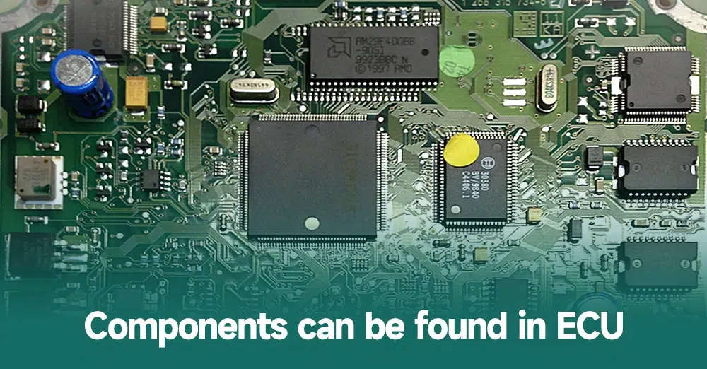
Step 5: ECU PCB Component Identification
Identifying components on an ECU PCB is a meticulous but essential process. Each component plays a specific role, and knowing what they are helps in understanding the circuit’s functionality. Here’s how to proceed:
- Resistors and Capacitors: Look for color bands on resistors to determine their values (e.g., a 1kΩ resistor) or markings on capacitors (e.g., 10uF). Use a multimeter to confirm values if markings are unclear.
- Integrated Circuits (ICs): Note the part numbers on ICs and search for datasheets online to understand their function (e.g., a microcontroller might be labeled as “MC9S12” with specific pin functions).
- Diodes and Transistors: Identify polarity markings on diodes and check transistor types (NPN or PNP) using a multimeter’s testing mode.
- Connectors: Document the purpose of each connector by tracing where they lead (e.g., a connector might link to engine sensors or the vehicle’s CAN bus).
If a component is unidentifiable, consider desoldering it carefully for closer inspection, but only as a last resort to avoid damaging the board.
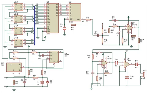
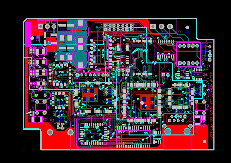
Step 6: Analyzing ECU PCB Schematics
Once you’ve documented the layout and identified components, the next step is to recreate the schematic – a diagram showing how components are electrically connected. This is the heart of reverse engineering. Follow these steps:
- Start with Power and Ground: Draw the power supply lines and ground connections first, as they form the backbone of the circuit.
- Map Component Connections: Use a multimeter in continuity mode to trace connections between components. For example, check if a resistor connects to a specific pin on an IC.
- Follow Signal Flow: Identify input and output signals (e.g., sensor inputs to the microcontroller or outputs to actuators) by tracing thinner signal lines.
- Use Software Tools: Input your findings into schematic drawing software to create a clean, organized diagram. Label each connection and component clearly.
For complex multi-layer boards, consider using X-ray imaging to reveal hidden traces, or carefully sand down layers if feasible (though this is destructive and should be a last resort).
Step 7: Testing and Validation
After recreating the schematic, validate your findings by testing the ECU PCB. Reconnect it to a power source (if safe) and use an oscilloscope to measure signals at key points. For instance, check if a clock signal on the microcontroller pin matches the expected frequency (e.g., 8MHz as per the datasheet). Compare your schematic with observed behaviors to ensure accuracy.
If discrepancies arise, revisit your documentation and traces to correct errors. This iterative process ensures your reverse-engineered schematic is as close to the original design as possible.
Step 8: Ethical and Legal Considerations in Automotive PCB Reverse Engineering
Reverse engineering an ECU PCB can raise ethical and legal questions, especially if done for commercial purposes or without permission. Always consider the following:
- Respect intellectual property rights and avoid using reverse-engineered designs for unauthorized replication or profit.
- Ensure your work complies with local laws regarding automotive electronics and vehicle modifications.
- Use reverse engineering for educational, repair, or personal purposes within legal boundaries.
Challenges in Reverse Engineering ECU PCBs
Reverse engineering an ECU PCB isn’t without challenges. Here are some common hurdles and tips to overcome them:
- Multi-Layer Boards: Internal layers are hard to trace without specialized equipment. Use X-ray imaging if available, or focus on external connections.
- Obscured Markings: Components with erased or unclear markings can be identified by testing their electrical behavior with a multimeter.
- Complex Firmware: While this guide focuses on hardware, remember that ECUs rely on firmware. Extracting or analyzing firmware may require additional skills like programming or debugging.
Tips for Successful Automotive PCB Reverse Engineering
To wrap up, here are some practical tips to enhance your reverse engineering process:
- Work methodically and document every step to avoid confusion later.
- Start with simpler sections of the PCB before tackling complex areas like the microcontroller.
- Join online forums or communities focused on automotive electronics for advice and shared knowledge.
- Practice on less critical or scrap PCBs to build your skills before working on a valuable ECU.
Conclusion
Reverse engineering an ECU PCB is a rewarding yet challenging endeavor that opens up a deeper understanding of automotive electronics. By following the steps outlined in this guide – from understanding the ECU PCB layout to analyzing schematics and identifying components – you can successfully uncover the design and functionality of an engine control unit. Whether your goal is repair, modification, or research, a systematic approach combined with the right tools will lead to success in automotive PCB reverse engineering.
Remember to prioritize safety, accuracy, and ethical considerations throughout the process. With patience and practice, you’ll gain valuable insights into the complex world of ECU design and functionality.