ALLPCB


In the fast-evolving world of automotive technology, flexible PCBs (Printed Circuit Boards) have become a game-changer, especially in infotainment systems. These lightweight, adaptable circuits are ideal for the compact and dynamic environments of modern vehicles. If you're wondering how flexible PCBs are used in automotive infotainment, this blog dives deep into their design, applications, and key considerations like material selection, bend radius, routing techniques, and dynamic bending. Whether you're an engineer or a tech enthusiast, you'll find practical insights to understand their role in creating smarter, safer, and more engaging driving experiences.
What Are Flexible PCBs and Why Are They Essential in Automotive Infotainment?
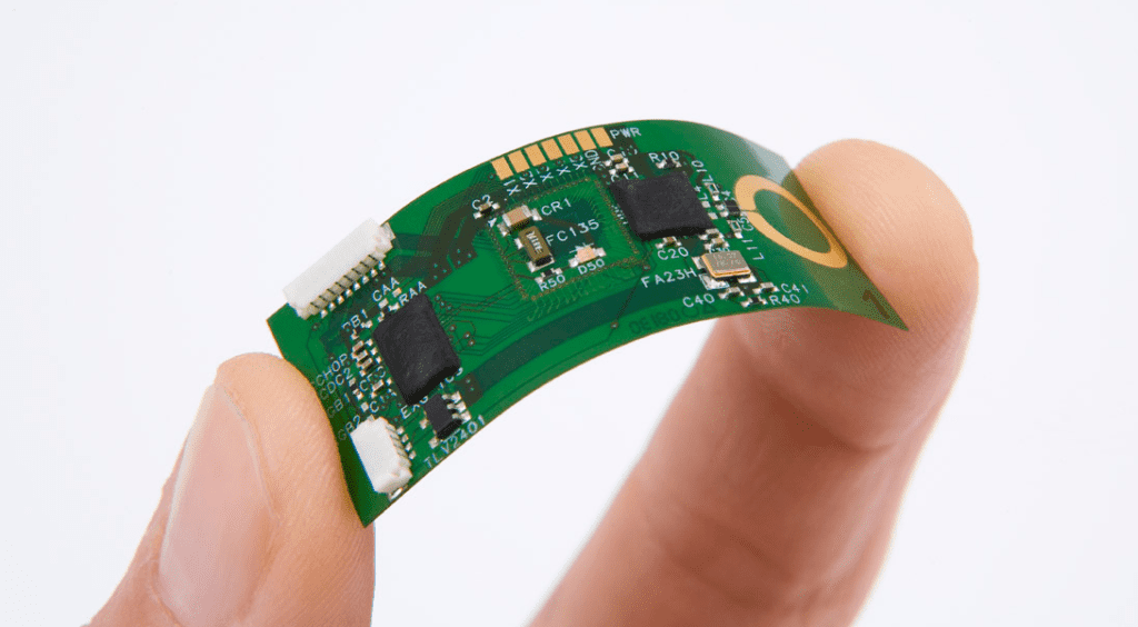
Flexible PCBs, often called flex circuits, are thin, bendable boards made from materials that allow them to conform to unique shapes and withstand repeated movement. Unlike rigid PCBs, they can fit into tight spaces and handle vibrations, making them perfect for automotive infotainment systems. These systems include touchscreens, navigation displays, audio controls, and connectivity modules that enhance driver and passenger experiences.
In vehicles, space is limited, and components must endure constant motion, temperature changes, and mechanical stress. Flexible PCBs solve these challenges by offering durability and design versatility. They reduce weight, simplify assembly, and improve reliability compared to traditional wiring or rigid boards. As cars become more connected with advanced driver-assistance systems (ADAS) and in-car entertainment, the demand for flex circuits continues to grow.
Key Applications of Flexible PCBs in Automotive Infotainment
Flexible PCBs are used in various parts of automotive infotainment systems due to their adaptability and compact nature. Here are some primary applications:
- Touchscreen Displays: Modern car dashboards often feature curved or foldable touchscreens. Flexible PCBs connect the display to the main control unit, allowing seamless integration into non-flat surfaces.
- Control Panels: Buttons and knobs for audio or climate controls use flex circuits to save space and ensure reliable connections despite frequent use.
- Connectivity Modules: With the rise of Bluetooth, Wi-Fi, and 5G in cars, flexible PCBs support compact antenna designs and high-speed data transfer in tight spaces.
- Lighting Systems: Ambient lighting in cabins often relies on flex circuits to fit along curved edges and provide uniform illumination.
These applications highlight how flex circuits enable innovative designs while meeting the strict reliability standards of the automotive industry. Their ability to handle dynamic bending applications ensures they perform well under constant movement, such as when a display panel adjusts or a control module vibrates during driving.
Flexible PCB Material Selection for Automotive Infotainment
Choosing the right materials for flexible PCBs is critical in automotive applications where performance and durability are non-negotiable. The materials must withstand harsh conditions like temperature swings from -40°C to 85°C, humidity, and mechanical stress. Let’s explore the key factors in flexible PCB material selection:
- Base Material: Polyimide is the most common choice for flex circuits due to its excellent thermal stability and flexibility. It can endure repeated bending without cracking and resists temperatures up to 260°C during soldering processes.
- Conductor Material: Copper is widely used for its conductivity and flexibility. Rolled annealed copper, with a thickness of 18 to 35 micrometers, is often preferred for dynamic applications as it bends better than standard electrodeposited copper.
- Coverlay and Adhesives: A polyimide coverlay protects the circuit while maintaining flexibility. Adhesive-less options are gaining popularity in automotive designs to reduce thickness and improve heat dissipation.
- Stiffeners: In areas requiring support, such as connector points, FR4 or metal stiffeners are added to prevent damage during assembly or use.
Material selection directly impacts the PCB’s ability to handle bending and environmental stress. For instance, a poorly chosen base material might crack under vibration, leading to signal loss in a navigation display. By prioritizing high-quality, automotive-grade materials, manufacturers ensure long-term reliability.
Bend Radius Considerations in Flexible PCB Design
One of the biggest advantages of flexible PCBs is their ability to bend, but this must be done within safe limits to avoid damage. Bend radius considerations are crucial to ensure the circuit’s integrity, especially in automotive infotainment systems where space constraints demand tight folds.
The bend radius is the minimum radius a flex PCB can be bent without stressing or breaking the copper traces or base material. It varies based on whether the application is static (bent once during installation) or dynamic (repeated bending during use). Here are the general guidelines:
- Static Bending: For a single-layer flex PCB, the minimum bend radius should be at least 6 times the board’s thickness. For a 0.1 mm thick board, this means a bend radius of 0.6 mm or more.
- Dynamic Bending: In applications like adjustable displays, the bend radius should be at least 10 times the thickness to account for repeated stress. For the same 0.1 mm board, aim for a 1 mm radius.
- Multilayer Designs: Multilayer flex PCBs require even larger bend radii, often 12-15 times the thickness, due to increased stress on internal layers.
Exceeding these limits can cause micro-cracks in copper traces, leading to signal interruptions. For example, in a car’s infotainment touchscreen that adjusts position, a too-tight bend could degrade touch sensitivity over time. Designers must balance compactness with safe bending limits to ensure performance.
Flex PCB Routing Techniques for Optimal Performance
Routing traces on a flexible PCB requires careful planning to maintain signal integrity and prevent damage during bending. Poor routing can lead to issues like crosstalk, impedance mismatch, or trace breakage. Here are some proven flex PCB routing techniques tailored for automotive infotainment systems:
- Curved Traces: Instead of sharp 90-degree turns, use curved or angled traces (45-degree angles) to reduce stress concentration during bending. This is especially important for high-speed signals in connectivity modules where data rates can reach 5 Gbps.
- Trace Width and Spacing: Maintain adequate spacing between traces to prevent crosstalk. For high-frequency signals, a trace width of 0.1 mm and spacing of 0.15 mm can help control impedance, typically targeting 50 ohms for single-ended signals.
- Teardrop Pads: Add teardrop-shaped pads at via connections to strengthen the joint and prevent cracking during flexing. This is vital near connectors in control panels.
- Avoid Traces in Bend Areas: Route critical traces away from high-stress bend zones. If unavoidable, use thinner traces or stagger them across layers to distribute stress.
- Ground Planes: Incorporate solid ground planes or hatched patterns beneath signal traces to minimize noise, especially for audio components where signal clarity is critical.
By applying these techniques, designers can ensure reliable performance even in tight automotive layouts. For instance, routing high-speed traces for a 5G antenna module with proper spacing prevents signal degradation, ensuring seamless connectivity for streaming or navigation.
Dynamic Bending Applications in Automotive Infotainment
In modern vehicles, infotainment systems often involve moving parts, such as adjustable screens or foldable displays. Dynamic bending applications are where flexible PCBs truly shine, as they can endure repeated flexing without failure. Let’s look at how they are applied:
- Adjustable Displays: Some luxury vehicles feature screens that tilt or slide based on driver preference. Flexible PCBs connect these displays to the main system, bending up to 10,000 cycles or more without losing conductivity.
- Hinge Connections: In foldable infotainment panels, flex circuits act as hinges, maintaining signal integrity across moving joints. They can handle bend radii as tight as 1 mm in dynamic setups.
- Vibration Resistance: Cars experience constant vibration, especially on rough roads. Flexible PCBs in audio control modules absorb these shocks, preventing connection loss.
For dynamic applications, the design must prioritize materials with high fatigue resistance, like rolled annealed copper, and adhere to larger bend radii. Testing under simulated conditions, such as 100,000 bending cycles at 25°C, ensures the PCB can withstand real-world use. This reliability is critical for safety features tied to infotainment, like rear-view camera displays.
Challenges and Solutions in Using Flexible PCBs for Automotive Infotainment
While flexible PCBs offer numerous benefits, they come with challenges that designers must address:
- Cost: Flex circuits are often more expensive than rigid boards due to specialized materials and manufacturing processes. Solution: Optimize designs to minimize material waste and use hybrid rigid-flex boards where full flexibility isn’t needed.
- Thermal Management: High-density infotainment components generate heat, which can degrade flex materials. Solution: Use adhesive-less laminates and integrate heat sinks or thermal vias.
- Signal Integrity: Bending and high-speed data can disrupt signals. Solution: Implement strict routing guidelines and test impedance (e.g., maintaining 50 ohms) during prototyping.
Addressing these challenges ensures that flexible PCBs deliver both innovation and reliability in automotive environments.
Future Trends: Flexible PCBs in Next-Gen Automotive Infotainment
The role of flexible PCBs in automotive infotainment is set to expand with emerging technologies. Here are a few trends to watch:
- Augmented Reality Dashboards: AR displays for navigation will rely on flex circuits to integrate into curved windshields or head-up displays.
- Flexible OLED Screens: As OLED technology advances, ultra-thin, bendable screens will use flex PCBs for seamless connectivity in futuristic cabin designs.
- Smart Surfaces: Touch-sensitive surfaces across dashboards and seats will incorporate flex circuits for compact, lightweight wiring.
These innovations will push the boundaries of flexible PCB material selection, bend radius considerations, and dynamic bending applications, driving the need for even more robust and adaptable designs.
Conclusion: Why Flexible PCBs Are the Future of Automotive Infotainment
Flexible PCBs are transforming automotive infotainment by enabling compact, durable, and innovative designs. From touchscreen displays to adjustable panels, their applications are vast, supported by careful considerations in flexible PCB material selection, bend radius considerations, flex PCB routing techniques, and dynamic bending applications. As vehicles become smarter and more connected, the importance of flex circuits will only grow, paving the way for safer and more immersive driving experiences.
At ALLPCB, we’re committed to supporting engineers with high-quality flexible PCB solutions tailored for automotive challenges. By understanding the design principles and applications outlined in this blog, you can create infotainment systems that meet the demands of today and tomorrow.