ALLPCB


Designing PCBs for power electronics in industrial automation is a critical task that requires careful attention to high-current handling, thermal management, material selection, and safety. Whether you're working on motor drives, power supplies, or control systems, a well-designed PCB ensures reliability and efficiency in demanding environments. In this comprehensive guide, we'll explore key aspects of power PCB design, including high-current PCB layout techniques, PCB materials for power electronics, thermal management in power PCBs, and safety considerations for power electronic PCBs. Let's dive into the details to help you create robust and efficient designs for industrial applications.
Why Power PCB Design Matters in Industrial Automation
Industrial automation systems often operate under harsh conditions, with high power demands, fluctuating loads, and extreme temperatures. Power electronics PCBs are the backbone of these systems, managing energy conversion, motor control, and signal processing. A poorly designed PCB can lead to overheating, electrical failures, or even safety hazards, causing costly downtime. By focusing on optimized power PCB design, you can ensure long-term performance and reliability, even in the toughest industrial settings.
Key Principles of Power PCB Design for Industrial Automation
Creating a PCB for power electronics involves balancing electrical performance, thermal efficiency, and mechanical durability. Below, we break down the essential principles to guide your design process.
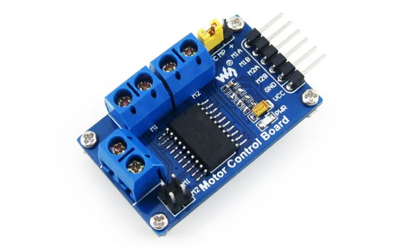
1. High-Current PCB Layout Techniques
Industrial automation often requires handling high currents, sometimes exceeding 50A, for powering motors or actuators. Proper layout techniques are crucial to minimize resistance, voltage drops, and heat generation. Here are some proven high-current PCB layout techniques:
- Wider Traces for Lower Resistance: Use wider copper traces to handle high currents. For example, a 1 oz copper layer might need a trace width of 200 mils (5 mm) to carry 10A safely at a temperature rise of 10°C. Online trace width calculators can help determine exact dimensions based on current and copper thickness.
- Short and Direct Paths: Keep high-current paths as short as possible to reduce parasitic inductance and resistance. Place power components close to each other to minimize loop areas.
- Copper Planes for Power Distribution: Dedicate entire layers or large areas as copper planes for power and ground. This reduces impedance and provides a low-resistance path for high currents.
- Via Stitching for Multi-Layer Boards: Use multiple vias to connect high-current traces across layers. For instance, placing 10-15 vias in parallel can significantly lower resistance and improve current handling.
By implementing these high-current PCB layout techniques, you can ensure efficient power delivery and prevent overheating in industrial systems.
Image Placement Suggestion: Include a diagram of a PCB layout with wide traces and copper planes for high-current paths. ALT Text: "High-current PCB layout with wide traces and copper planes for industrial automation."
2. Choosing the Right PCB Materials for Power Electronics
The choice of PCB materials for power electronics directly impacts performance, especially in industrial automation where high power and heat are common. Standard FR-4 materials may not suffice for high-current or high-temperature applications. Consider the following options and factors:
- High Thermal Conductivity Materials: Materials like aluminum-backed PCBs or ceramic substrates offer better heat dissipation than standard FR-4. For instance, aluminum PCBs can have thermal conductivity up to 2.0 W/m·K compared to FR-4’s 0.3 W/m·K.
- Thicker Copper Layers: Opt for 2 oz or 3 oz copper layers instead of the standard 1 oz to handle higher currents with less resistance and heat buildup.
- High Tg Materials: Use materials with a high glass transition temperature (Tg) of 170°C or more to withstand elevated temperatures without deforming. This is critical for industrial environments where ambient temperatures can exceed 85°C.
- Dielectric Strength: For high-voltage applications, select materials with high dielectric strength to prevent breakdown. Polyimide-based materials are often used for such scenarios.
Selecting the right PCB materials for power electronics ensures durability and reliability, even under the stress of industrial automation systems.
Image Placement Suggestion: Add an image comparing different PCB materials, such as FR-4 versus aluminum-backed boards. ALT Text: "Comparison of PCB materials for power electronics in industrial automation."
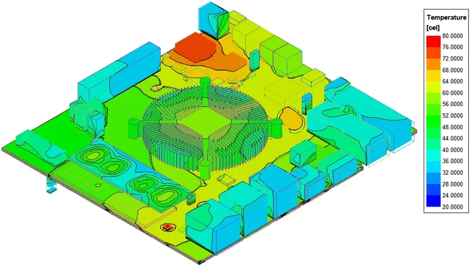
3. Thermal Management in Power PCBs
Thermal management in power PCBs is a top priority, as excessive heat can degrade components, reduce lifespan, and cause system failures. Industrial automation systems often generate significant heat due to high power dissipation. Here are effective strategies for managing heat:
- Heat Sinks and Thermal Vias: Attach heat sinks to high-power components like MOSFETs or IGBTs. Use thermal vias under these components to transfer heat to other layers or a heat sink. For example, a grid of 0.3 mm vias with 1.2 mm spacing can improve heat dissipation by up to 30%.
- Component Placement: Place heat-generating components away from sensitive parts like microcontrollers. Distribute high-power components evenly across the board to avoid hot spots.
- Copper Pour for Heat Spreading: Use large copper areas near power components to spread heat across the board. A copper pour on the top and bottom layers can act as a passive heat dissipater.
- Forced Air or Liquid Cooling: In extreme cases, integrate fans or liquid cooling systems into the design. Ensure the PCB layout allows for airflow by avoiding tall components that block vents.
Effective thermal management in power PCBs keeps your industrial automation systems running smoothly, even under heavy loads.
4. Safety Considerations for Power Electronic PCBs
Safety is non-negotiable in industrial automation, where high voltages and currents pose risks to equipment and personnel. Addressing safety considerations for power electronic PCBs during the design phase can prevent catastrophic failures. Key safety practices include:
- Creepage and Clearance Distances: Maintain adequate spacing between high-voltage traces to prevent arcing. For example, at 500V, a clearance of at least 6 mm is often required per industry standards like IPC-2221.
- Overcurrent Protection: Integrate fuses or circuit breakers to protect against short circuits. Place these near the power input to limit damage in case of a fault.
- Grounding and Shielding: Implement proper grounding to reduce electromagnetic interference (EMI) and ensure safety. Use ground planes and shielding for sensitive signals near high-current areas.
- Insulation and Conformal Coating: Apply conformal coatings to protect against moisture, dust, and accidental contact in harsh industrial environments. Ensure high-voltage areas are insulated to prevent shocks.
By prioritizing safety considerations for power electronic PCBs, you can build designs that protect both the system and the people who operate it.
Best Practices for Designing Power PCBs in Industrial Automation
Beyond the core principles, adopting best practices can elevate your power PCB design process. These tips are tailored for industrial automation challenges:
- Simulation and Testing: Use simulation tools to model thermal and electrical performance before manufacturing. Test prototypes under real-world conditions to validate your design.
- Modular Design: Design your PCB in modular sections for easier maintenance and upgrades. For instance, separate power and control sections to isolate high-current noise from sensitive signals.
- Compliance with Standards: Follow industry standards like IPC-2221 for trace spacing and current handling, and IEC 60950 for safety in power electronics. Compliance ensures reliability and market acceptance.
- Minimize EMI: Route high-current traces away from sensitive analog or digital circuits. Use differential signaling for critical data lines to reduce noise pickup.
These best practices streamline the design process and result in PCBs that meet the rigorous demands of industrial automation.
Common Challenges and Solutions in Power PCB Design
Designing PCBs for power electronics in industrial automation comes with unique challenges. Here are some common issues and how to address them:
- Challenge: Overheating in High-Power Applications
Solution: Combine active cooling (fans) with passive methods (heat sinks, thermal vias). Optimize component placement to avoid thermal stacking. - Challenge: Voltage Drops in High-Current Paths
Solution: Use thicker copper layers and wider traces. Implement power planes to distribute current evenly across the board. - Challenge: EMI in Mixed-Signal Designs
Solution: Separate analog, digital, and power sections. Use ground planes and shielding to isolate noise sources.
Understanding these challenges and their solutions helps you anticipate problems and design more robust PCBs.
Conclusion: Building Reliable Power PCBs for Industrial Automation
Designing PCBs for power electronics in industrial automation is a complex but rewarding process. By focusing on high-current PCB layout techniques, selecting the right PCB materials for power electronics, prioritizing thermal management in power PCBs, and adhering to safety considerations for power electronic PCBs, you can create designs that withstand the rigors of industrial environments. Remember to leverage simulation tools, follow industry standards, and test thoroughly to ensure your PCB performs reliably under real-world conditions.
With these strategies, you're well-equipped to tackle the challenges of power PCB design and contribute to efficient, safe, and durable industrial automation systems. Keep refining your skills and staying updated on the latest advancements in PCB technology to stay ahead in this dynamic field.