 ALLPCB


In industrial settings, printed circuit boards (PCBs) face extreme challenges like scorching heat, intense vibrations, moisture, and electromagnetic interference (EMI). Designing high-reliability PCBs for these harsh environments is critical to ensure consistent performance and prevent costly failures. This guide offers a deep dive into creating durable PCBs tailored for tough conditions, covering key aspects such as material selection, protective coatings, and EMI shielding. Whether you're working on industrial automation or heavy machinery, you'll find practical tips to build robust electronics that withstand the toughest environments.
Why High-Reliability PCB Design Matters in Industrial Environments
Industrial environments are unforgiving. From factories with high humidity to outdoor systems enduring temperature swings, PCBs must operate flawlessly under stress. A single failure can halt production, costing thousands in downtime. High-reliability PCB design addresses these risks by focusing on durability, thermal management, and protection against environmental factors. In this blog, we'll explore proven strategies for industrial PCB design for extreme temperatures, PCB materials for vibration resistance, and other critical areas to ensure your boards thrive in harsh conditions.
Key Challenges in Harsh Industrial Environments
Before diving into solutions, let's break down the primary challenges PCBs face in industrial settings:
- Extreme Temperatures: Industrial equipment often operates in environments ranging from -40°C to 85°C or higher, risking thermal expansion and component failure.
- Vibration and Mechanical Stress: Heavy machinery generates constant vibrations, which can loosen components or crack solder joints.
- Moisture and Corrosion: Humidity and chemical exposure can degrade PCB materials and cause short circuits.
- Electromagnetic Interference (EMI): Industrial settings are filled with motors and power systems that emit EMI, disrupting signal integrity.
Addressing these challenges requires a multi-layered approach, from material selection to protective measures. Let's explore each solution in detail.
1. Industrial PCB Design for Extreme Temperatures
Temperature extremes can warp boards, degrade components, and disrupt electrical performance. Designing PCBs for extreme temperatures starts with understanding thermal management and material properties.
Choosing the Right Substrate Materials
Standard FR-4 materials, commonly used in consumer electronics, often fail under high heat due to their glass transition temperature (Tg) of around 130°C. For industrial applications, consider high-Tg FR-4 (Tg of 170°C or higher) or advanced materials like polyimide, which can withstand temperatures up to 260°C. These materials resist thermal expansion, with coefficients of thermal expansion (CTE) as low as 12-14 ppm/°C, reducing stress on components during temperature swings.
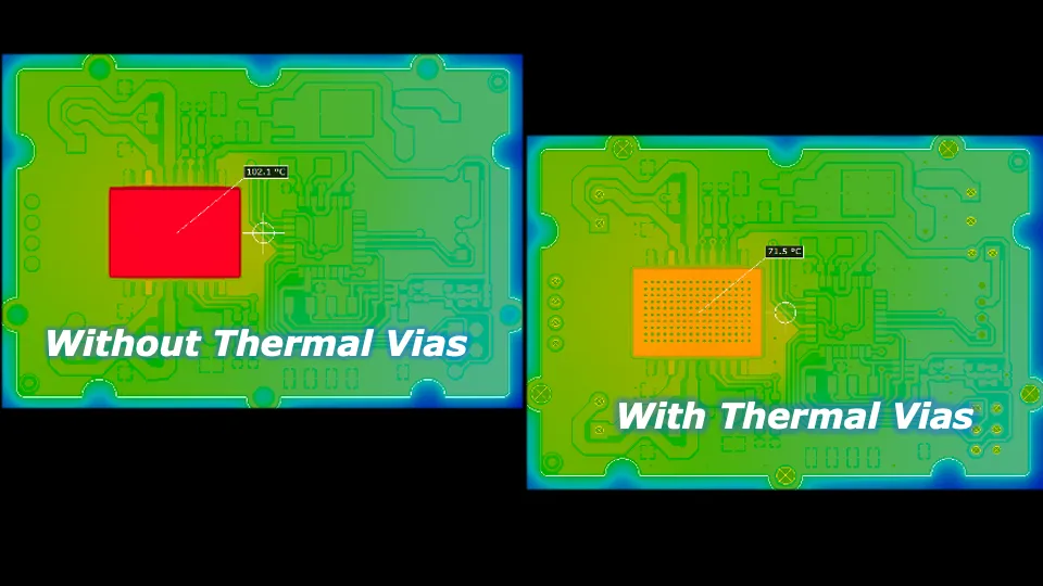
Thermal Management Techniques
Beyond materials, thermal design is crucial. Incorporate heat sinks or thermal vias to dissipate heat from high-power components. For example, placing thermal vias with a diameter of 0.3mm in a grid pattern under a power IC can reduce junction temperatures by up to 20°C. Additionally, ensure adequate spacing between heat-generating components to prevent hotspots.
2. PCB Materials for Vibration Resistance
Vibrations from industrial machinery can cause mechanical failures like cracked solder joints or detached components. Building vibration-resistant PCBs requires robust materials and thoughtful design.
Selecting Durable Materials
Thicker PCB substrates, such as 2.0mm or 2.4mm FR-4, provide greater structural integrity compared to standard 1.6mm boards. Additionally, using flexible-rigid or pure flex PCBs can absorb mechanical stress in high-vibration areas. These materials reduce the risk of board flexing, which can lead to trace fractures.
Component Placement and Mounting
Strategically place components away from board edges or mounting holes where stress concentrates. Use adhesives or underfill for larger components like capacitors to secure them against vibration. For instance, applying an epoxy underfill to a BGA package can increase its shear strength by 50%, preventing detachment during operation.
Also, consider using locking mechanisms or dampening mounts for the PCB itself to minimize direct vibration transfer from the equipment housing. Testing under MIL-STD-810 vibration standards can validate your design’s durability, ensuring it withstands frequencies up to 2000 Hz.
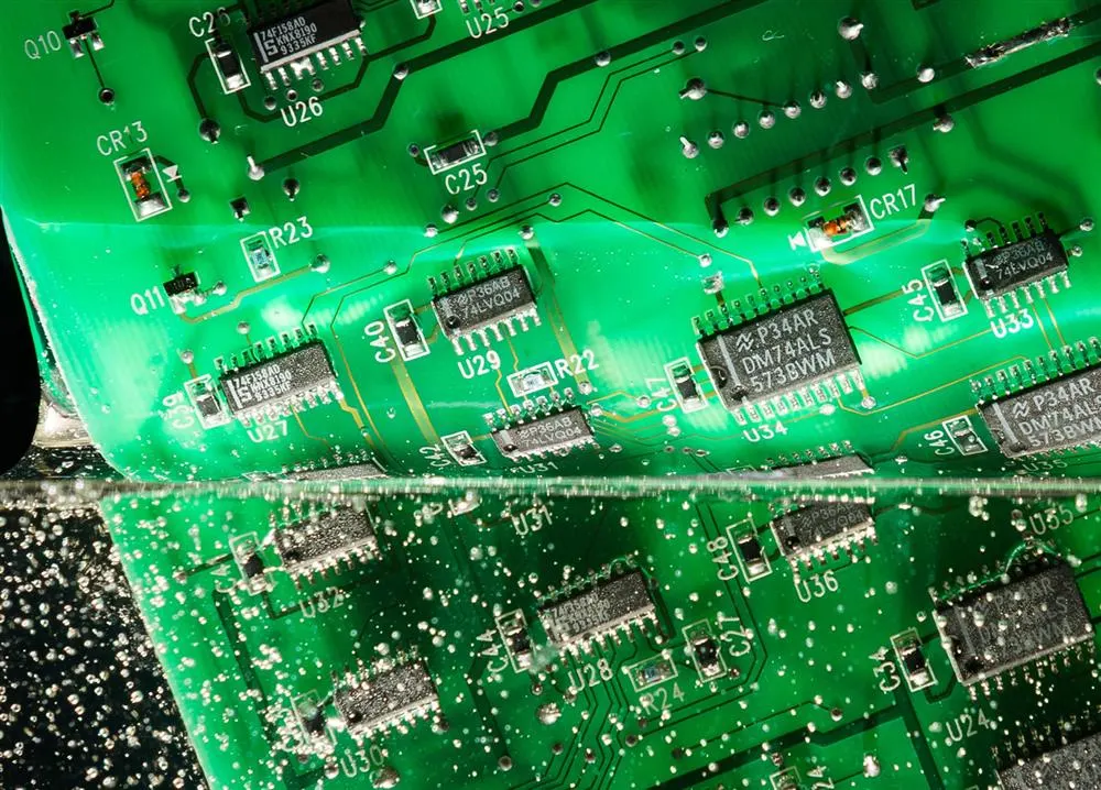
3. Conformal Coating for PCB Moisture Protection
Moisture, dust, and chemicals are constant threats in industrial environments, leading to corrosion and short circuits. Conformal coating for PCB moisture protection acts as a barrier, safeguarding your board from these hazards.
Types of Conformal Coatings
Conformal coatings are thin polymeric films applied to PCBs to shield against environmental damage. Common types include:
- Acrylic: Easy to apply and rework, offering good moisture resistance for moderate environments.
- Silicone: Highly flexible and heat-resistant, ideal for temperature extremes up to 200°C.
- Polyurethane: Excellent chemical resistance, perfect for harsh industrial settings with solvent exposure.
- Parylene: A vapor-deposited coating providing superior protection but harder to apply and remove.
Coating thickness typically ranges from 25 to 75 micrometers, depending on the environment. For high-humidity areas, a thicker coating (closer to 75 micrometers) ensures better insulation.
Application Tips
Ensure thorough cleaning of the PCB before coating to remove contaminants like flux residue, which can trap moisture underneath. Use selective coating techniques to avoid covering connectors or test points. Automated spray or dip methods provide uniform coverage, critical for consistent protection.
4. PCB Design for Electromagnetic Interference (EMI) in Industrial Settings
Industrial environments are often noisy with EMI from motors, power lines, and other equipment. Unchecked EMI can corrupt signals, causing data errors or system malfunctions. Effective PCB design for electromagnetic interference (EMI) in industrial settings minimizes these risks.
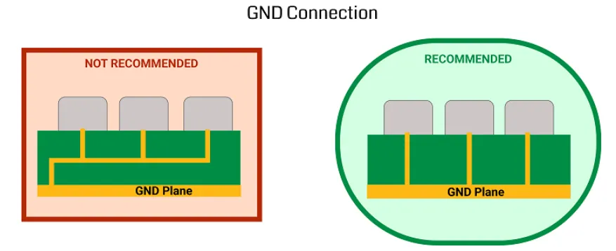
Grounding and Shielding Strategies
A solid ground plane is the foundation of EMI protection. Use a continuous ground layer beneath signal traces to reduce noise coupling. For high-frequency signals (above 100 MHz), implement a split ground plane to separate analog and digital sections, preventing interference between them.
Shield critical components with metal enclosures or conductive coatings. For example, a Faraday cage around sensitive RF modules can block external EMI, reducing signal noise by up to 30 dB. Route high-speed traces away from board edges to avoid acting as antennas that pick up or emit interference.
Filtering and Component Selection
Incorporate EMI filters, such as ferrite beads or common-mode chokes, near power entry points to suppress noise. Choose components with low EMI signatures, like shielded inductors, to minimize radiated emissions. Ensure trace impedance matches the system (e.g., 50 ohms for RF signals) to prevent reflections that amplify EMI.
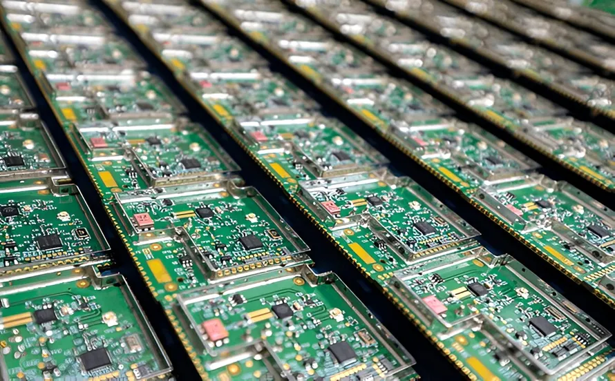
5. Ruggedized PCB Components for Industrial Automation
Industrial automation systems demand components that endure harsh conditions without failing. Selecting ruggedized PCB components for industrial automation is a vital step in ensuring long-term reliability.
Choosing Robust Components
Opt for components with extended temperature ratings, such as industrial-grade ICs rated for -40°C to 105°C, compared to commercial-grade parts limited to 0°C to 70°C. Use ceramic capacitors instead of electrolytic ones in high-vibration areas, as they resist mechanical stress better and have lower failure rates.
Connectors should be locking or high-retention types to prevent loosening under vibration. For power applications, select MOSFETs or IGBTs with high avalanche energy ratings (e.g., 500 mJ or more) to handle voltage spikes common in industrial power systems.
Redundancy and Derating
Build redundancy into critical circuits by using parallel components to maintain functionality if one fails. Apply derating practices by operating components below their maximum ratings— for instance, running a capacitor at 50% of its rated voltage doubles its lifespan in high-stress conditions.
Testing and Validation for Harsh Environments
Designing a PCB is only half the battle. Rigorous testing ensures it performs reliably in real-world conditions. Conduct environmental stress tests, including thermal cycling from -40°C to 85°C, to simulate temperature extremes. Use vibration tables to test under frequencies up to 2000 Hz, mimicking industrial machinery.
Perform humidity tests at 85% relative humidity for 1000 hours to verify moisture protection. EMI testing, following standards like CISPR 25, confirms your design resists interference. Document failure points and iterate on the design to address weaknesses, ensuring the final product meets industry standards like IPC-A-610 for acceptability of electronic assemblies.
Conclusion: Building PCBs That Last in Harsh Industrial Environments
Designing high-reliability PCBs for harsh industrial environments requires careful attention to every detail, from material selection to protective coatings. By focusing on industrial PCB design for extreme temperatures, using PCB materials for vibration resistance, applying conformal coating for PCB moisture protection, optimizing PCB design for electromagnetic interference (EMI) in industrial settings, and selecting ruggedized PCB components for industrial automation, you can create boards that stand up to the toughest conditions.
Start with robust materials and thoughtful layouts, then reinforce your design with protective measures and rigorous testing. With these strategies, your PCBs will deliver consistent performance, reducing downtime and ensuring operational success in even the most demanding industrial applications. Trust in a comprehensive approach to PCB design, and your electronics will be ready to tackle any challenge.


